You see all these Home Security systems being advertised all the time and they all have one gotcha. Some kind of charge every month. Why not just make your own? Also it costs PENNIES on the dollar compared to some of those others.
One of the biggest components of home security is knowing the state of windows and doors. And that is very simple to obtain and with INEXPENSIVE hardware. This guy is the backbone to this project:
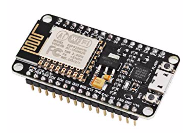
This is a NodeMCU ESP8266 Internet of Things (IoT) chip. Translation: It’s a little teeny tiny small board computer with a wifi antenna on it.
You can get ESP8266 devices WAY cheaper than this even though this guy only costs $9 or so. A couple of things I like about it are that it has a Micro USB input connector on it and the legs are already soldered on.
This makes it the simplest of all the ESP8266 chips to use. if you use another chip you may have to solder the legs on. Not a problem for me, but maybe a problem for you. Also to program these chips they have to be placed in boot loader mode. On some chips that involves holding one GPIO pin to ground as it starts up. Sometimes there is a button and sometimes you have to do it manually. The procedure is different for different boards. With this NodeMCU chip you just plug in a microUSB cable and run your Arduino code. It does everything for you.
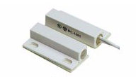
This chip is SIMPLE for the first time user. Next we need a reed switch. That’s a switch that when it comes in contact with it’s magnet that it flips from on to off or vice versa. As the window goes up the sensor switch moves away from the magnet and the state of the switch changes. I use these excellent reed switches. A pack of ten costs $14.
 Okay, I’m going to make some assumptions. The first is that if you are reading this page trying to make sensors that you are a MAKER!. They used to call us geeks or nerds, and now we are MAKERS.
So as a maker you are probably running home automation software such as HomeAssistant or OpenHab or have a SmartThings hub. I use Home Assistant. Also to really make this work you need an MQTT server. I’m not going to go into MQTT servers here but they are a breeze to set up on almost every platform (Windows, Linux, Mac).
Now we need the code for the NodeMCU. For this project we’re going to use Tasmota and ArduinoIDE. Go to the Tasmota Releases page and download the latest Source Code.zip file. This is just a tiny snip of the list under the release.
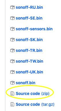
Just trying to keep it simple.
Also, download and install ArduinoIDE and install the ESP8266 Additional Boards as per the bulleted list below the screenshot on the left.
Then we will be ready to load some code.
- Start Arduino and open Preferences window.
- Enter
http://arduino.esp8266.com/stable/package_esp8266com_index.jsoninto Additional Board Manager URLs field. You can add multiple URLs, separating them with commas. - Open Boards Manager from Tools > Board menu and find esp8266 platform.
- Select the version you need from a drop-down box.
- Click install button.
- Don’t forget to select your ESP8266 board from Tools > Board menu after installation
Now unzip and open the Source Code folder (I’m doing this on a Mac) and do this:
So after you install Arduino IDE and download the Source Code.zip file you need to unzip the file and move it to where Arduino can find the libraries it needs. (Also I’m working on the assumption that you’ve used Arduino before and know how to flash an Internet of Things (IoT) chip.
Anyway navigate to the Sonoff Tasmota folder > lib and then copy everything inside that folder and move it to the Arduino Library folder.
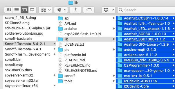
The folder location on my Mac is Documents > Arduino > Libraries. Just dump all those folders there.
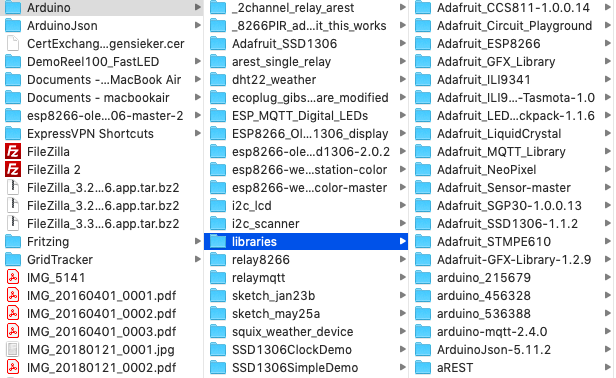
Now go back to your unzipped source code folder and open the sonoff folder and then double click the sonoff.ino file.

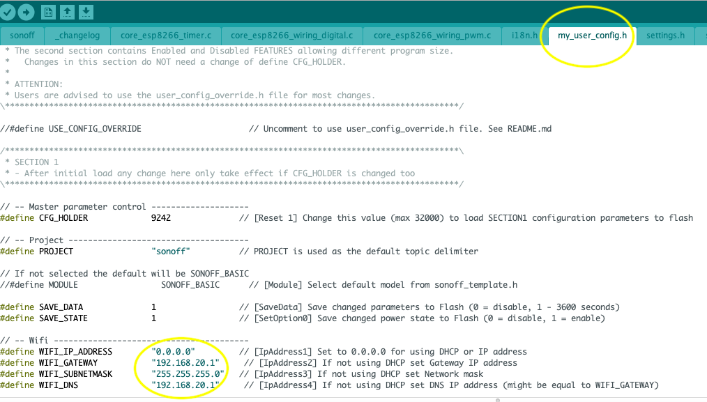
Now click on the tab that says my_user_config.h and look through the file and add your wifi network SSID and password, also configure your MQTT server data here if you like. Then when you flash it will automatically hook up to your network and you can start to configure it. At a minimum you should add your wifi credentials, if not you won’t be able to find it to configure it. Configure your SSID, password and set a static IP address. (Mine are not visible in the pic below for obvious reasons). Also notice in the pic below I have changed the DNS address and Gateway address to 192.168.20.1 because that reflects my network details. Make sure the IP addresses match your network here. 0.0.0.0 means it will grab any DHCP address the router gives it.
Configure my_user_config.h (click to enlarge)
Now lets upload the code. Set Arduino up like this:
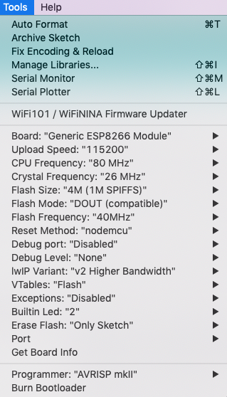
The only real missing piece of the puzzle here is the field labelled “Port”.
Make sure you set the correct port.
Now we are ready to compile and upload our code.
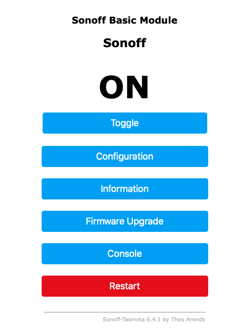
Once you get the code loaded you have to find the device on your wifi. Open your router config, use an app like Fing or LanScan or connect or open the Serial Monitor under Tools in the ArduinoIDE software. Once you find your IP address just type it in a Browser. It should look like this when you open it:
Now go to the Configuration button and click it and then click the CONFIGURE MODULE button and set the module type to Generic (18). Heck while we are at it set the D6 GPIO12 to “Switch1 (09) and hit save. (Ignore my Temperature Sensor on D5 GPIO14, but that shows you how versatile this Tasmota is).
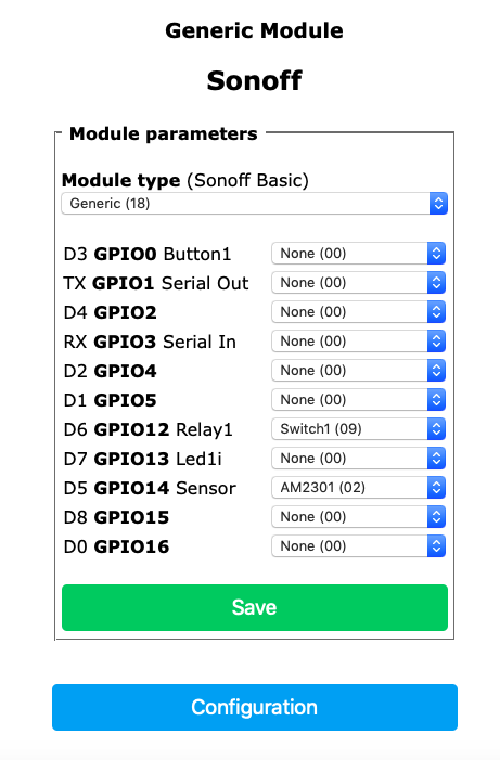
Configured! Once it restarts take the two white wires on your reed switch and hook them up with one wire to Pin D6 and the other wire to a Ground (GND)
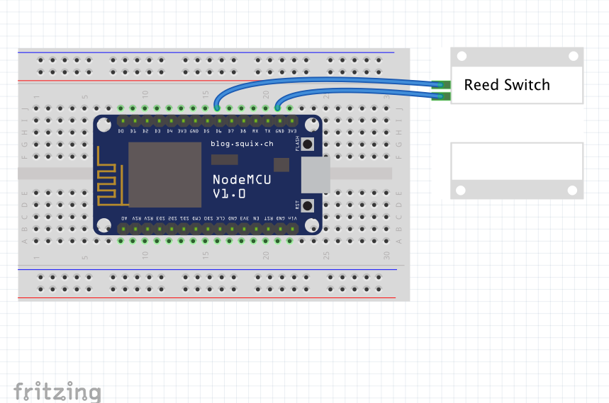
Fritzing is cool!
Go back to the Main Configuration page and hit the “CONFIGURE MQTT” button. Set your MQTT server up. Again I’m not discussing MQTT servers here.
Now your code is loaded and your switch hooked up. You may not see anything going on but as you move that magnet away from and back towards the reed switch your MQTT server will be getting those messages.
Here’s my MQTT server watching for all my messages. You can see the switch turn off and on. That is me just pulling the magnet away from the reed switch a few times.
[kad_youtube url=”https://youtu.be/Aw91Yd8nF30″ ]
With automations you can do the following things (and more)…….have an audible alarm go off. Have it text you, turn the lamp on in your bedroom in the other room. Turn the lights on in the room where the window opened (scare tactic). Sky is the limit here.
I’ll publish some HomeAssistant code later when I get to installing this.
Oh, last thing……Remember when I said “ignore the temperature sensor” earlier. I have a DHT11 temp and humidity sensor that I plugged in just for fun. It looks like this:
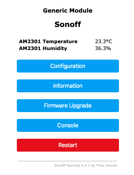
Pretty nifty, huh?

Thanks for some really informative articles John. I played around with Lua and Micropython on my ESP8266 devices but now the Tasmota actually allows me to do something useful with a BME280 sensor. MQTT was also straightforward, now I just need to figure out what to use for the HomeAssistant on one of my Raspberry PIs.
John, this is exactly what i was looking for. i have a wemos mini sensing fridge and freezer door status plus a dht22. Home assistant picks the status up via MQTT. i am using ESPEasy. Problem is that if the weoms resets, it starts misbehaving i.e. doesnt detect anything. thta could be due to one of the reed switches connecting to TX RX i think. I have to reattach the power and ground to the sensors while Wemos is running to make them work. anyways. with youre instructions i will redo the project. I will probably remove DHT22 because the readings are too high anyways as compared to the actual temperature in the kitchen as it sits atop the fridge. BTW with this setup, i announce via google home mini speakers if we have forgotten to shut the fridge or freezer.
Thanks.
Whats the maximum number of reed switches that can be added? What pics do we need to use for that?
Good idea. What about battery power for ESP? I hope such battery board exists as popular solution.
Thanks so much for this, a really useful guide.
I skipped a lot and just used Tasmotizer to get the nodemcu ready then followed the rest of your guide, it’s kinda magical when stuff works 🙂
I even tried Tasmotizer and still failed. I followed the instructions to the T and just keep getting errors. Tasmotizer won’t run.
Really struggling to find the version of Tasmota you downloaded. Most show “Source Code (zip)” under “Tasmota.bin” not “Sonoff.bin” and then don’t contain a sonoff.ino file. I’ve seached and searched for the version in the link you provided and nothing.
Actually, Tasmota project used to publish its files under the name “Sonoff.bin”, as a matter of common sense they are now named “Tasmota.bin” so you can go ahead and download those, they’re the same thing.
It’s NOT “common sense”. The version of Tasmota these instructions use is very old and things have changed dramatically. At this point, even if you figure out to use the “tasmota” folder and “tasmota.ino” (NOT .bin”), it still doesn’t work because some important files haven’t been imported so the compile fails. Also you gloss over the process of importing the Tasmota libraries into the Arduino IDE, which is a long way from being obvious, especially since it is a manual import and not the one the official Arduino documentation recommends with .zip files.
I’m extremely disappointed because I’m trying to get a very simple motion detector working on a local MQTT server I have running on my own Web server. Everybody wants to complicate things with third-party MQTT servers and other stuff that doesn’t make any sense. Seriously, if you’re rolling your own hardware why on earth would you want to go to a third party for operation? Especially when that will cause your entire system to fail in the case of an Internet problem, whereas if it’s running on your own home server it will hum along quite happily as long as there’s power and your own LAN is up.
The new version won’t work if you follow these instructions because you won’t be grabbing all of the files needed. You’ll get errors about missing dependencies.
I know this thread is starting to age, but I’ll give it a try. I must be missing something.. I did the whole process (used GPIO14 -> Switch 1 (9), tasmota console detect the ON/OFF of the door sensor. Also home assistant mqtt console detects the device but nothing else. Do I need to run additional commands in tasmota console ? Do I need to configure a yaml file or anything else in home assistant ? Thanks in advance.