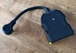
 Found another somewhat easily Tasmota flashable Outdoor plug. It is the Etekcity ESO15-TB, (approximately $20). It can only be flashed via serial to USB and oddly enough I found no good solid guide online for flashing it. When I opened it up I saw that it had an ESP-01E chip. I also discovered that it required a complete disassembly to get to the bottom of the board.
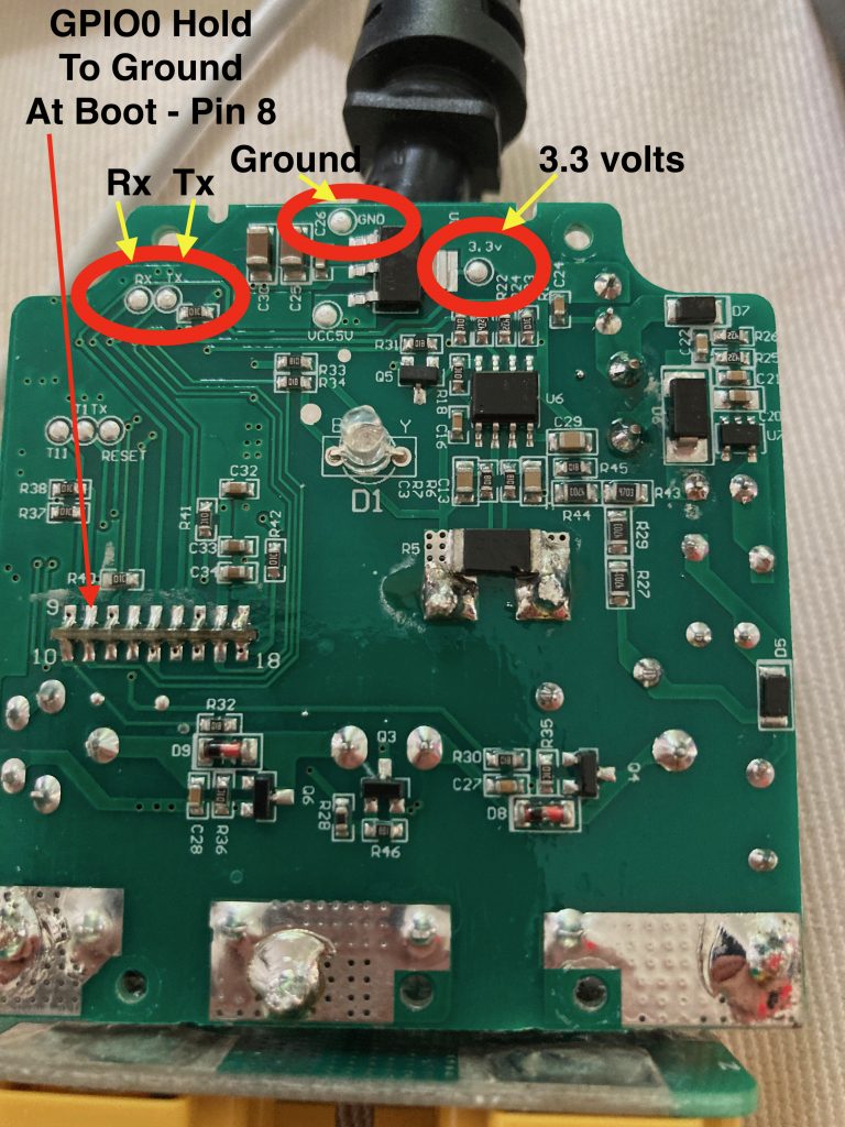
When I first flipped it over I thought all was lost because the ESP-01E is kind of a plug in module and the solder points are SUPER close together. Closer than my 59 year old eyes can navigate, at least not without mumbling some special words I learned in the Navy. A closer inspection revealed clearly marked test points with the exception of GPIO0 which almost always has to be held to ground to put the chip into boot loader mode. The pinout in the ESP-01E doc shows that GPIO0 is pin 8.
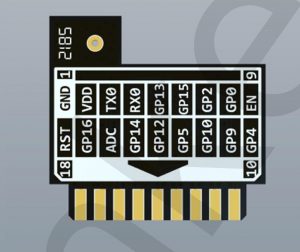
ESP-01E Pinout
And I confirmed this by looking at the chip itself.
So here is the location of the test points:
Etekcity Outdoor Plug Programming Points (click pic to enlarge)
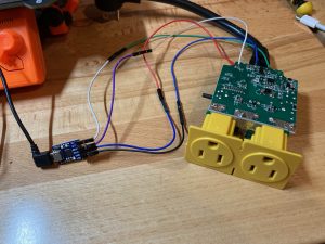
When you just power up via the FTDI controller the LED light flashes blue. When you successfully hold Pin 8 to Ground during power up to get into boot loader mode the LED will be amber (yellow) color. Then you can flash Tasmota.bin. I flashed mine via ESP-FLasher on a Mac.
Once you have it booted connect to the hotspot it transmits called Tasmota with some random numbers and navigate to 192.168.4.1 in a browser. It will ask you for your wifi credentials, reboot and give you the IP address that it assigned on your network. Navigate to that IP address and enter the following Template data in Configuration > Configure Other > Template Line. Be sure to click the ACTIVATE button after you paste the template and then hit save.
{"NAME":"ES015-TB","GPIO":[0,0,0,0,224,225,288,0,2656,2688,32,2592,289,0],"FLAG":0,"BASE":18}
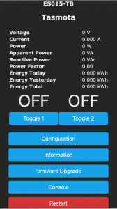
Now when it reboots it will look like this:
Bingo-desu. You have Tasmotized your Etekcity Outdoor Plug.

I noticed, upon following your template, that the button on the side only turned on outlet 1. I added a simple rule to toggle both relays on button press: rule1 on button1#state do backlog power1 %value%; power2 %value%; endon
Thanks for the guide! Made everything very straight forward and simple.
I like what Shynd did, but I prefer an alternate setup for the button:
rule1 on button1#state=2 do backlog power1 1; power2 1; endon
rule2 on button1#state=3 do backlog power1 0; power2 0; endon
rule1 1
rule2 1
setoption32 20
savedata