I run RTL_433 to push data from several sensors and a motion detector to an MQTT server for home automation. For some reason as of late it is just not that stable. Could even be a hardware failure with the dongle….I dunno. I generally just run the program command inside a terminal on the raspberry pi it is installed on and just walk away. When it crashes I have to log back in the Pi and re-run the command. Un-cool.
The command I use specifically is this:
rtl_433 -F json -M utc | mosquitto_pub -t home/rtl_433 -l
Again, that pushes data found on 433.920 MHz devices to publish a topic on my MQTT server called “home/rtl_433”.
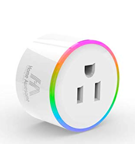
Found these cool little outlets on Amazon and verified they can be flashed with Tasmota Over The Air (OTA). They are technically called “Home Awesome Breathing Light Smart Light.
They are another made in China device that is controlled via phone app and I generally don’t trust such things. Flashing the device with Open Source firmware is MUCH better for securities sake.
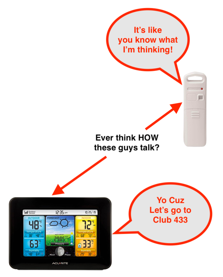
Last week I showed you how you can capture the remote codes for cheap radio controlled electrical outlets and this week the theme is 433 MHz MOTION SENSORS. With a properly configured motion detector you can then trigger that outlet. For example……..when you open the pantry door the light comes on………when you walk in the laundry room, the light comes on……..when someone presses the smart doorbell, the lights come on. Pretty handy stuff.
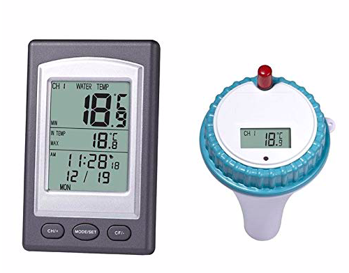
Most home automation motion sensors send TWO signals. One when they are tripped and one when they reset. Most of them will stay tripped for a predetermined amount of time. Usually for 2-4 minutes or so. Good idea to know the state of the motion detector BEFORE you buy it.
For example I have a motion detector with a 4 minute reset on it in my garage and laundry closet. That means that both of those lights that get triggered are staying on for 4 minutes whether I like it or not (unless I write some crazy code).
But some of these cheap sensors send ONE signal. “I’m ON” and that’s it. They don’t reset. That provides a challenge. This is one such sensor I bought (and DEFEATED).
It costs about $12 now and you can get them even cheaper. I got this for an outside sensor.
Anyway it does have some user control as inside there are two DIP switches. One sets the sensor state for 5 seconds or 5 minutes and the other one turns the LED indication it has been tripped on or off.
If you want to be stealthy, turn off the LED. I personally like the bad guys to know they got got.
Anyway before you can do this you must capture the code with a program called RTL_433. I discussed this in another blog.
RTL_433 And Home Assistant Set Up
MQTT 433 MHz Motion Sensor
Once your hardware is set up (an RTL-SDR device) you run this command on that pi to send THIS code below. The last part would only be necessary if your mosquitto MQTT server is on another device. Mine is.
Now that will take all the messages it receives from the SDR device (on 433.920 MHz) then it publishes a message on your MQTT server that looks like this:
Now we have to extract that data to make sure we hone in on this device (because I have multiple devices on this same MQTT Topic). In your HomeAssistant configuration.yaml file you add the following to create a binary sensor.
binary_sensor:
  - state_topic: home/rtl_433
    name: Garage Motion
    value_template: >
    {% if value_json is defined and value_json.id == 924442 %}
       {{ value_json.state }}
    {% endif %}
    payload_on: 'motion'
    off_delay: 5
    qos: 1
Whew! You can see I have it so it only takes information from sensor id #924442 and when the “state” = “motion” then it triggers the binary sensor. Then the line with:
off_delay: 10
Sets the sensor back to the OFF position after 10 seconds. So with a ONE signal sensor I can turn the state to OFF after how ever many seconds I want. That garage light will now go out after 1 minute or 2 minutes or 2 seconds……..whatever I want.
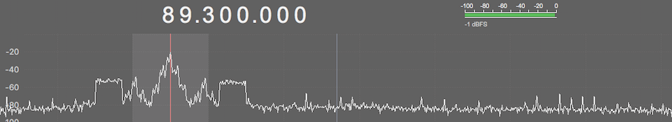
Well……It works PERFECTLY. Here’s what the tripped state looks like:
Now I can start making some automations to use with my $10 motion sensor. Open the pantry door……..the light comes on……….hence the name “Pantry Motion”.
Automations For 433 MHz Motion Sensor
So what I did here was to make an automation to turn on one of my inexpensive outlets. Eventually this will be tied to a smart light or smart switch. Right at this moment I have no smart light nor have installed a smart switch in the pantry. Changing the line of the entity_id in the action part of the code can turn basically any device on or off. Because the code above leaves the sensor state on for 10 seconds, running the automation means the “light” (in this case outlet) will be on for 1 minute. Pretty cool, huh?
automation 21:
  alias: Den Outlet Motion Sensor
  trigger:
    platform: state
    entity_id: binary_sensor.pantry_motion
    to: 'on'
#  condition:
#      condition: state
#      entity_id: sun.sun
#      state: below_horizon
  action:
    service: switch.turn_on
    entity_id: switch.den_outlet
automation 22:
- alias: Den Outlet Motion Sensor Off
  trigger:
    platform: state
    entity_id: binary_sensor.pantry_motion
    to: 'off'
    for: '00:00:50'
  action:
    service: switch.turn_off
    entity_id: switch.den_outlet
Notice that I have # marks in front of the condition statements. In many cases you wouldn’t want a light to come on until after dark. I left that in there to easily change it back if I find I don’t need the light on in the daytime, but hey, it is essentially a windowless closet.
Here’s a video of how it all works. I shortened the sensor time for the purpose of the video.
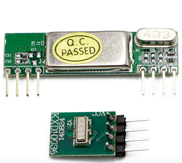
I’ve been dabbling with 433 MHz devices over the past few days and tying those devices in with my home automation software named HomeAssistant. A decent transmitter receiver kit will set you back a whopping $10 or so. I opted for this one.
It performs extremely well in a home environment and has great specs.
One of the gotchas of this device though is it comes with ABSOLUTELY NO DOCUMENTATION WHATSOEVER. You’d be hard pressed to find much useful on line as well. So that’s where I come in.
Fortunately the wiring is pretty basic and the pins are clearly marked on the back side of the circuit boards.
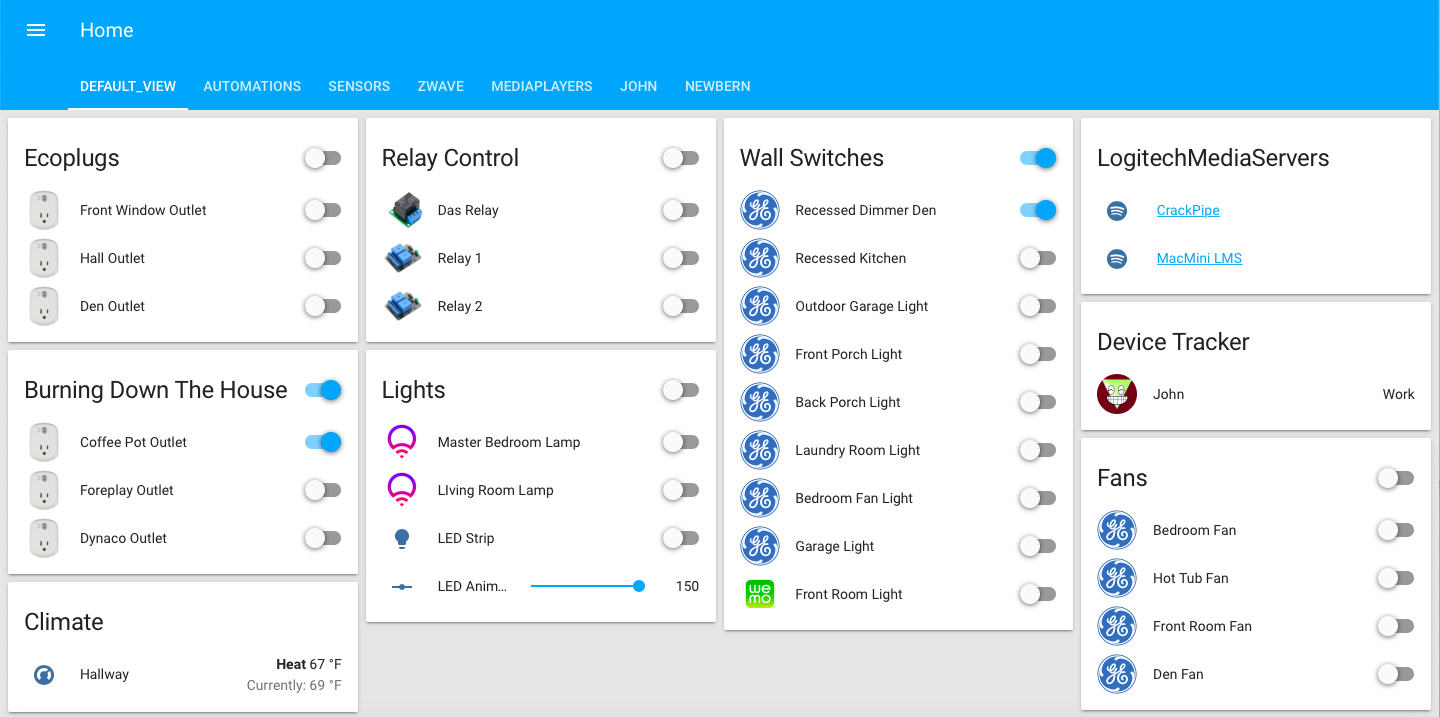
I have what I consider to be a pretty extensive Home Automation setup.
I use the program HomeAssistant on a Raspberry Pi3 with an Aeotech ZWave controller . Also I have some wifi devices such as a Nest Thermostat, Ring Doorbell, Ethernet Security Cameras, a WiFi Light Switch, and some smart light bulbs.
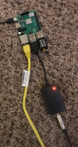
Ok I’ve been on a roll playing with OP25 and Raspberry Pi and one thing I can tell you is that the onboard audio from the bcm2835 chip is somewhat inadequate. Oh, it works but you’re going to need a powered speaker or really efficient headphones, and even then it is a bit light.
What to do?
Add a USB Digital to Analog converter (DAC). Depicted here is a HiFiMeDIY USB DAC. This is a tad bit expensive for this project but I have like 4 of these things laying around the house. They are ridiculously good. If you like music slap one of these bad boys on your laptop in the hotel room and the quality of your music will improve ten fold.
That’s not what we’re doing here though.
There are a LOT of USB DAC’s out there and some cost just a few dollars. HiFiMeDIY makes some cheaper ones as well that are way more than enough for improving your OP25 sound.
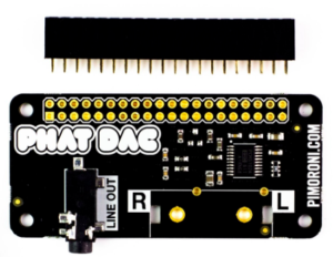
The Phat DAC costs $15 but you’ll have to solder header pins on yourself. That may be the cheapest, and best route. It has the form factor for the Raspberry Pi Zero but it works on all the Pi’s.


 The Replay Attack is when you record a signal from something and transmit it back to perform the operation.