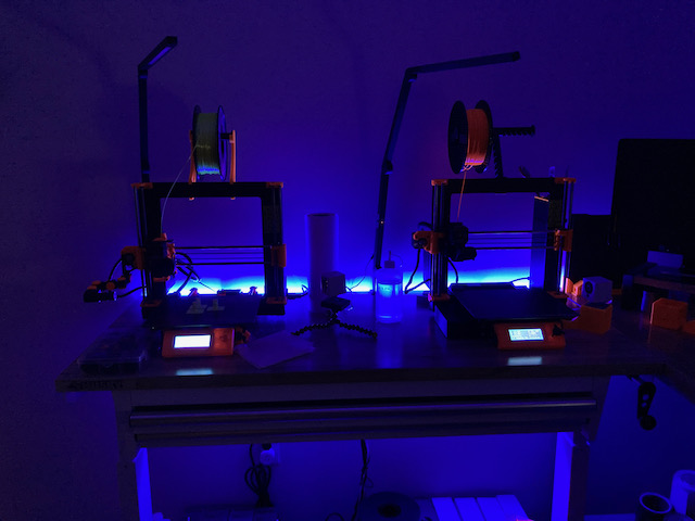
LED Effect Lighting
We’ve all seen those decorative LED strips in the big box stores. They are either controlled by a remote (who needs another remote control?) or by an app. I am here to tell you that the cheap Chinese lights and their apps are essentially spyware.
So to be safe we want to use an Open Source solution to power our lights. Enter, WLED by Aircookie. Before we go down the rabbit hole I want you to realize that this isn’t the typical geek project.
It is EASY! Anyone can do this. But to make it easy you’ll need a few things that could be optional if you cannot solder or you don’t have a drawer full of electronic geek stuff.
BEFORE I TALK TOO MUCH AND SCARE YOU OFF WE ARE GOING TO DO THIS ESSENTIALLY:
- PLUG IN A CHIP TO A COMPUTER
- OPEN A PROGRAM AND FLASH THAT CHIP WITH ONE BUTTON CLICK
- HOOK UP 5 WIRES
There are a lot of different LED strips and your selection will depend on what you are doing. Because I put a 4′ strip behind a workbench I used 5 volt strips. If you are doing a pretty long run, a 5 volt strip might not power all your lights without additional power injection. 12 volt strips MIGHT also require a level shifter on the data wires to get the signal down stream. Your ESP8266 chip will send a 3.3v data signal out. To make a long run you might need 5 volts. A level shifter turns a 3.3 volt signal into a 5 volt signal. But I digress. Let’s keep this simple.
On to the Build Of Materials:
My example will be for 5 volt strips. But basically………The same applies to 12 volt strips, just make sure you have a 12 volt power supply. And don’t put a 12 volt power supply on a 5 volt strip. POOF!
- LED Lights – I recommend these WS2812B lights. These are 5mm narrow strips. They make them in 10mm widths also. Either one will work. They are 6.6′ long with 120 lights.
- ESP8266 WiFi Chip – I like the NodeMCU chips for a lot of reasons I won’t go into here. You can get smaller, and cheaper chips. Again, I like these.
- Power Supply 5 volts (optional) – This ALITOVE 5v, 5 amp supply is a decent one and has the connectors you will need. This can be purchased in 10 amp or 15 amp if required. The reason I said “optional” above is that there are choices here. You probably have a million old devices in a box in the attic that has 5v USB chargers. I power mine with a USB cable that I cut one end off of and soldered the cable to the LED strip. My work bench has a power strip that has several 3 amp USB outlets.
- Barrel Connectors (optional) – Barrel Connectors The power supply above has one barrel connector with it so you may not need them at all. If you are running several strips……you need more than one.
- Breadboard wires – Get these wires to connect the ESP8266 chip to the LED strip. You can get cheaper wires and in not as large of a kit. Basically you need Male to Female 10 or 20 cm long wires.
That’s it. In a nutshell I bought the lights and I have a drawer full of NodeMCU’s and old USB cables. I didn’t need to buy any of that other stuff.
Now, let’s start with the ESP8266. One of the reasons I like the NodeMCU is that it has a Micro USB connector on it for power and programming. If you use a lesser chip you may need an FTDI USB to TTL Serial Converter to program it. (Just get the NodeMCU, huh?)
Download a program called “ESPHOME FLASHER“. There is a Windows and Mac version. I use Mac and when I downloaded the program it said there was a permissions error. The file wasn’t executable. Easy fix. Drag the application into your Applications folder and then in a terminal run this command.
chmod +x /Applications/ESPHome-Flasher.app/Contents/MacOS/ESPHome-Flasher
Most folks probably have Windows and I did promise to keep this easy.
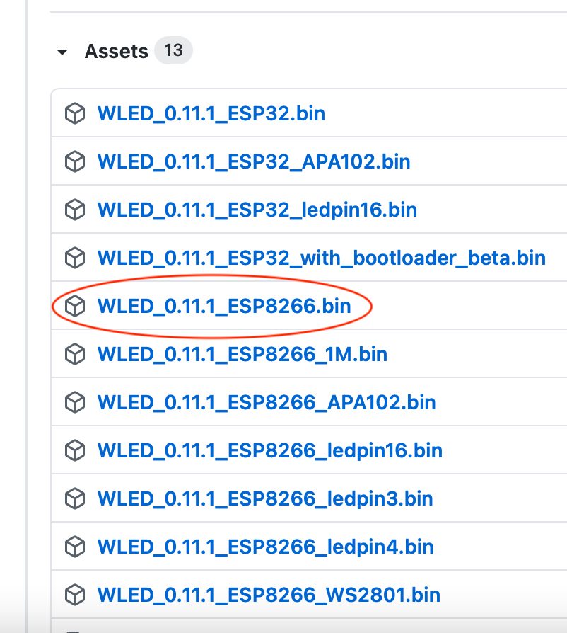
Now download the firmware to flash to the chip. Get it here. Download the .bin file that ends in “ESP8266.bin”
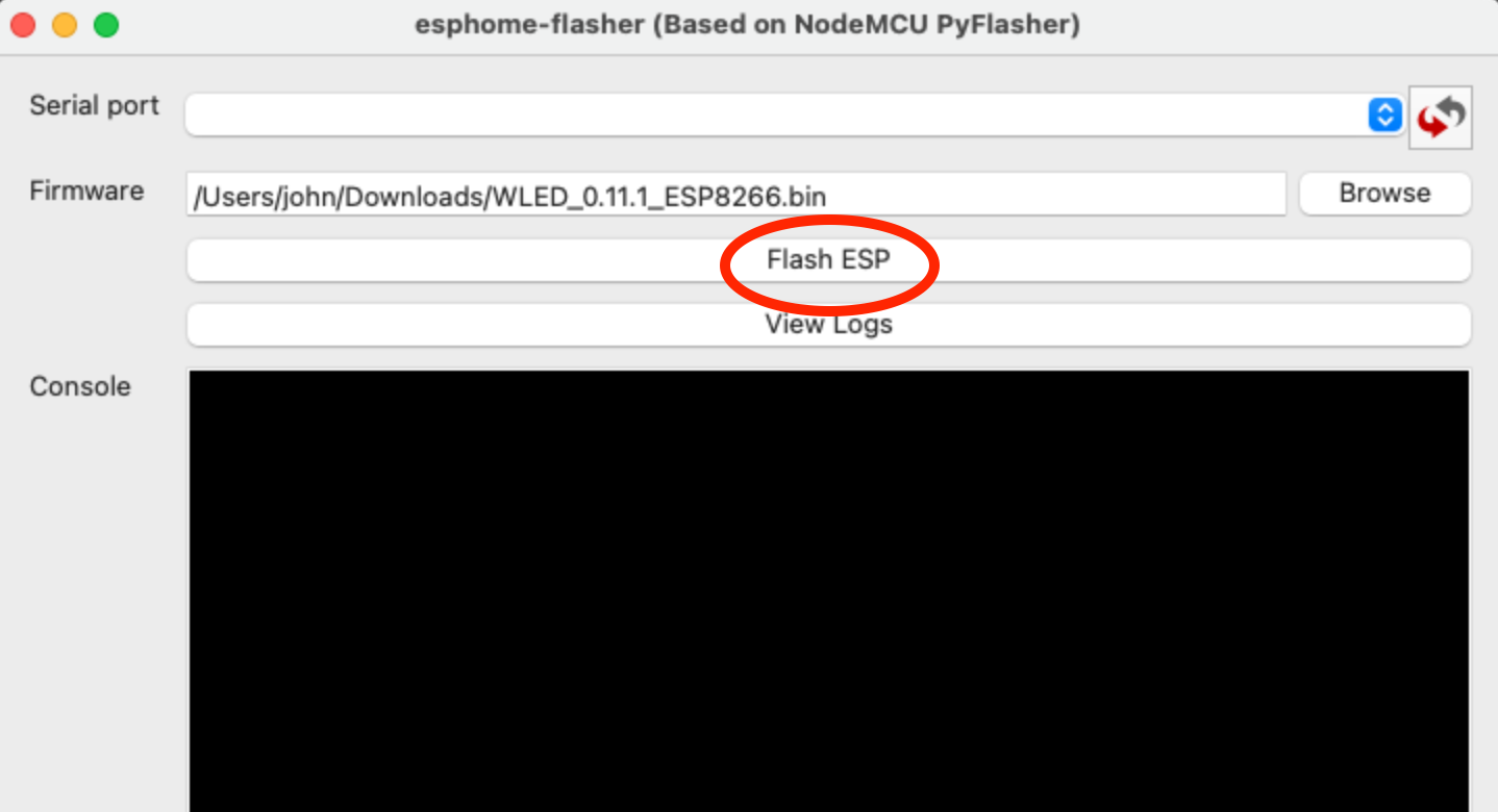
Now plug your NodeMCU into your computer and open ESPHome Flasher and select your device (not shown in my example below) and the .bin file you just downloaded. Then just hit “Flash”. That’s it. That’s all.
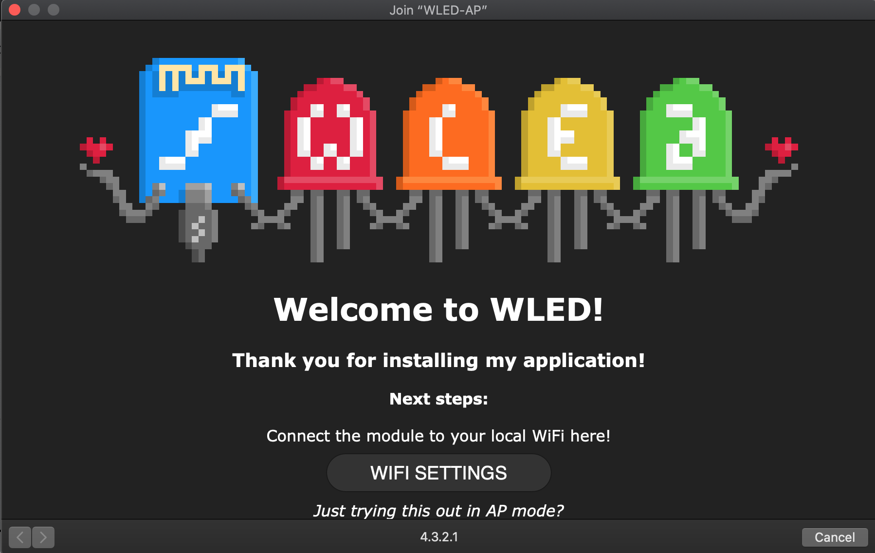
Connect to the device by finding the WiFi network it is broadcasting. As soon as you hook up to it (It’ll be called WLED-AP or something like that) a box will pop up.
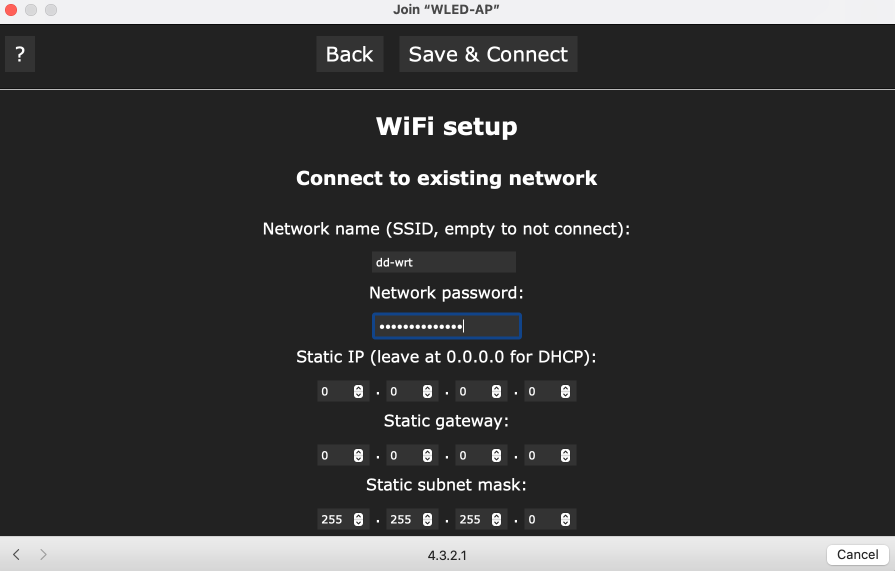
Click the “WiFi Settings Button and input your wifi credentials into the Network Name and Password boxes.
Now we can find the device. Unplug it and plug it back in. Go to a browser and type:
http://wled.local
Should look like this: (if that didn’t work you can find the IP of your NodeMCU and put that in the browser. i.e. Mine was 192.168.1.22)
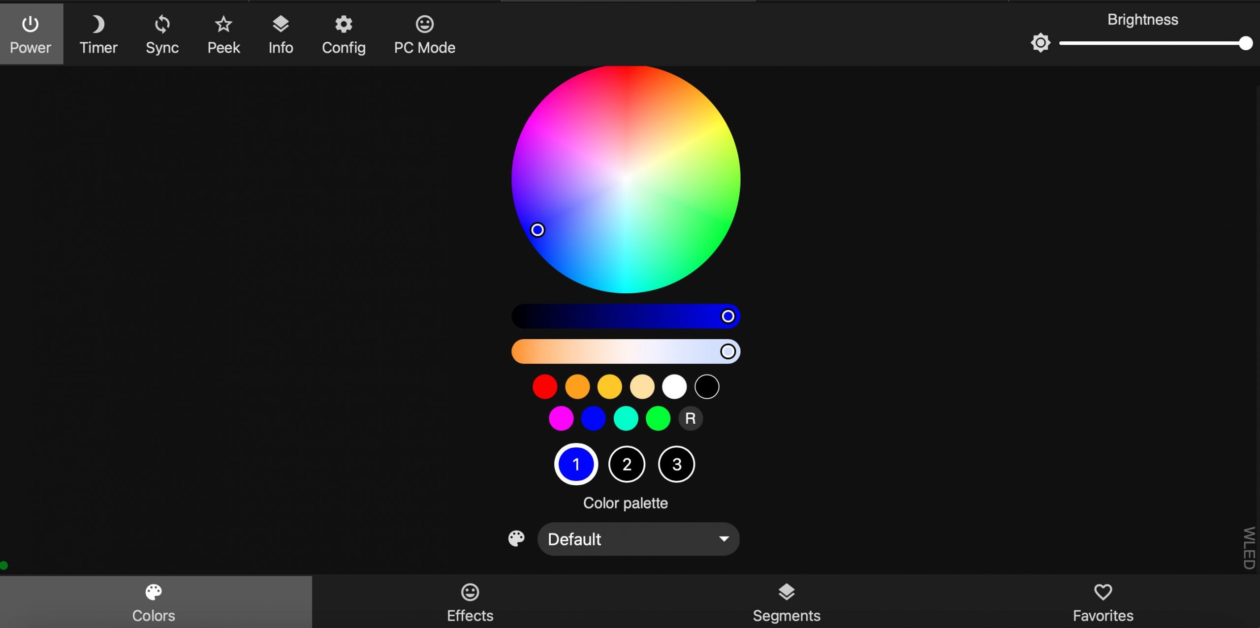
Ya Did It! Now all we have to do is hook up the lights.
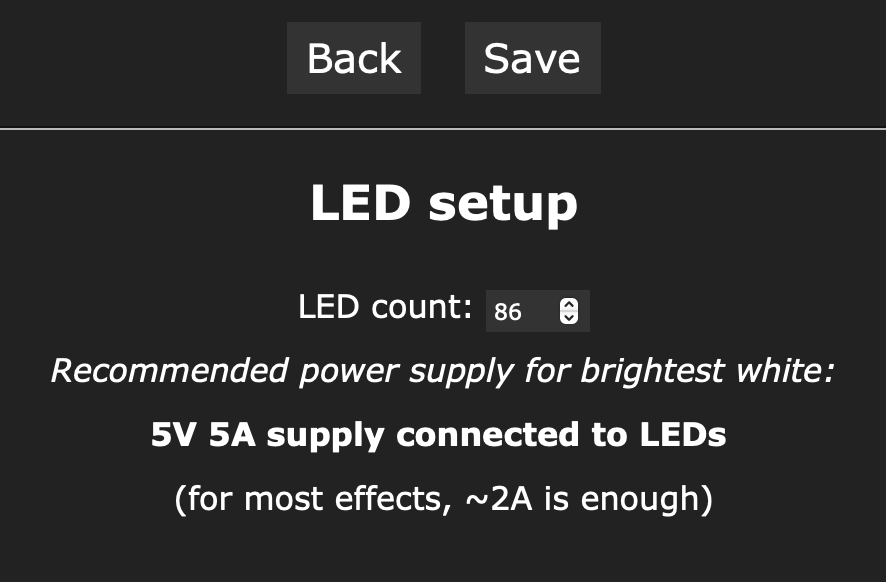
I WANNA SAY THIS IN BIG AND CAPITAL LETTERS. WHEN YOU HOOK YOUR LIGHTS UP WLED HAS A SETTING THAT ONLY TURNS ON 30 LIGHTS. FIRST TIME I DID THIS I THOUGHT I HAD A BAD LED STRIP.
On the top bar go to Config > LED Preferences and change the count to 120. (Mine says 86 because I cut my strip down to 4′ long). If you configure 120 and they don’t all come on……..you need more power, Captain. (said in your best Star Trek Scotty voice).
Now lets hook them up. 3 wires.
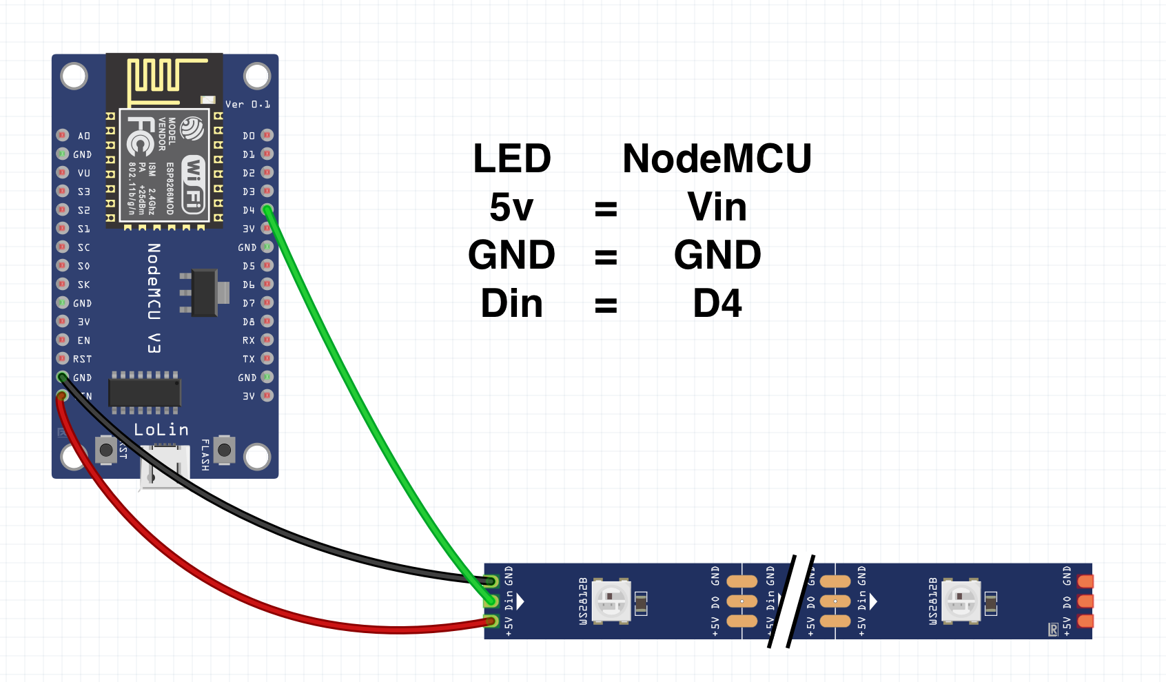
WS2812B wiring
It will look like this in real life. Notice I put some heat shrink on mine so the breadboard wires won’t come out easily.
NodeMCU to LED Wiring (click pics to enlarge)


Now with the two remaining wires, put your red wire in the barrel connector to the + pin and the white wire to the – pin.
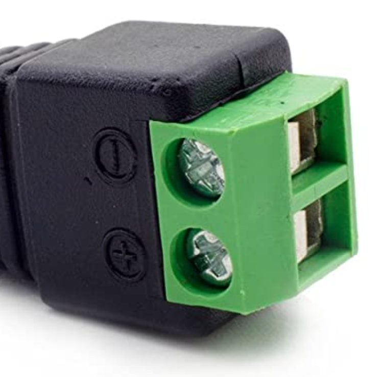
Barrel Connector
I only have a stock pic because, like I said, I cut a USB cable and wired red to red and white to black (on the usb cable) and soldered them together.
Because you used a barrel connector all you have to do is plug in your power supply.
Now go back to:
http://wled.local
(or the IP address of the NodeMCU)
And CONTROL YOUR LIGHTS BECAUSE YOU ARE DONE!
I won’t get into the steps here but if you run Home Assistant for Home Automation you can integrate WLED into it EASILY! It’s super cool!
[kad_youtube url=”https://youtu.be/a3PLIyNAnGo” ]
Great post, John! I’ve been looking into WLED lighting for my home and it’s great to see some practical examples of how it can be used. I especially loved the section on color temperatures and how they can affect mood and energy levels. Can’t wait to try out some of these ideas in my own home! 😊