Uniden SDS200 GPS
WHEN BUYING A GPS MODULE FOR THE SDS200 KNOW THAT GPS CHIPS ARE WILDLY COUNTERFEITED AND THAT BUYING A CHIP FROM AMAZON, EBAY, OR ALIEXPRESS IS LIKELY TO GET YOU A FAKE OR A REBRANDED CHIP.
I’ve been on a Uniden Police Scanner GPS DIY tear lately and my last radio scanner to need a GPS accessory is my prized Uniden SDS200. Sure you can buy a GPS unit for about $50, but our goal is to make one for less than that.
Oddly enough, this was the easiest one to make. Here’s what you need:
- GPS Module STM32 (not serial) – $12. NOTE: The previous GPS I had linked is no longer available. This one should work but I haven’t actually bought this one. It is probably counterfeit as well. Also on these breakout boards there is usually a chip for flash memory for upgrading the firmware. If no flash memory exists you won’t be able to upgrade.
- Any 4 wire RJ14 telephone cord. You can get them at Walmart for about $4. I’d be willing to bet you have one laying around in a junk drawer or hooked to an old phone you’ll never use again.
- 3D printed case (optional)
Oddly enough I bought a NEO-6M board from one seller on eBay for $8 and it is authentic which really surprised me. The NEO-6M is a pretty old chip though so I guess I’m not surprised old authentic stock is still out there. An $8 NEO-6M is HIGHLY RECOMMENDED for this project……..if you can find one.
Conversely, lots of different GPS units will work but they must not be serial devices. Additionally, make sure you get a 3.3 Volt, TTL logic unit and not an RS-232 serial device.
Let’s wire it up!
SDS200 Wiring Details
Here are the pinouts for the SDS200:
1: GPS TX
2: Ground
3: GPS RX
4: 3.3 Volt
SDS200 GPS Port Oriented Correctly (click pic to enlarge)

On your RJ14, four conductor telephone wire you MUST figure out what color wire goes to which pin. The RCA wire I bought at Lowes is color coded as per the picture below. And the picture above of the SDS200 GPS port on the scanner is color coded to match. BEWARE WHAT COLOR WIRES YOU HAVE AND WHAT PINS THEY GO TO.
Lastly, the pic below is flipped to show the color codes. Note that if I flip it horizontally to fit into the SDS200 connector the color coded wires match up.
RJ15 RCA Telephone Wire (click pic to enlarge)

I cut and trimmed my telephone cable and tested that there was 3.3 volts across the Black (+) and Green (-) wires. Actually there was about 3.8 volts there.
So now we just have to wire up the GPS unit itself. Easy money.
- Hot to Hot
- RX to TX
- Ground to Ground
- TX to RX
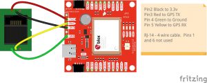
Fritzing Diagram
Looks like this:
GPS Module Wiring (click pic to enlarge)

Finally, make sure that your GPS is set up correctly. Go to Menu > Set Your Location > Set Up GPS > Set Serial Port. Select 9600 bps.
And when done, we dropped it in a nice 3D printed case.
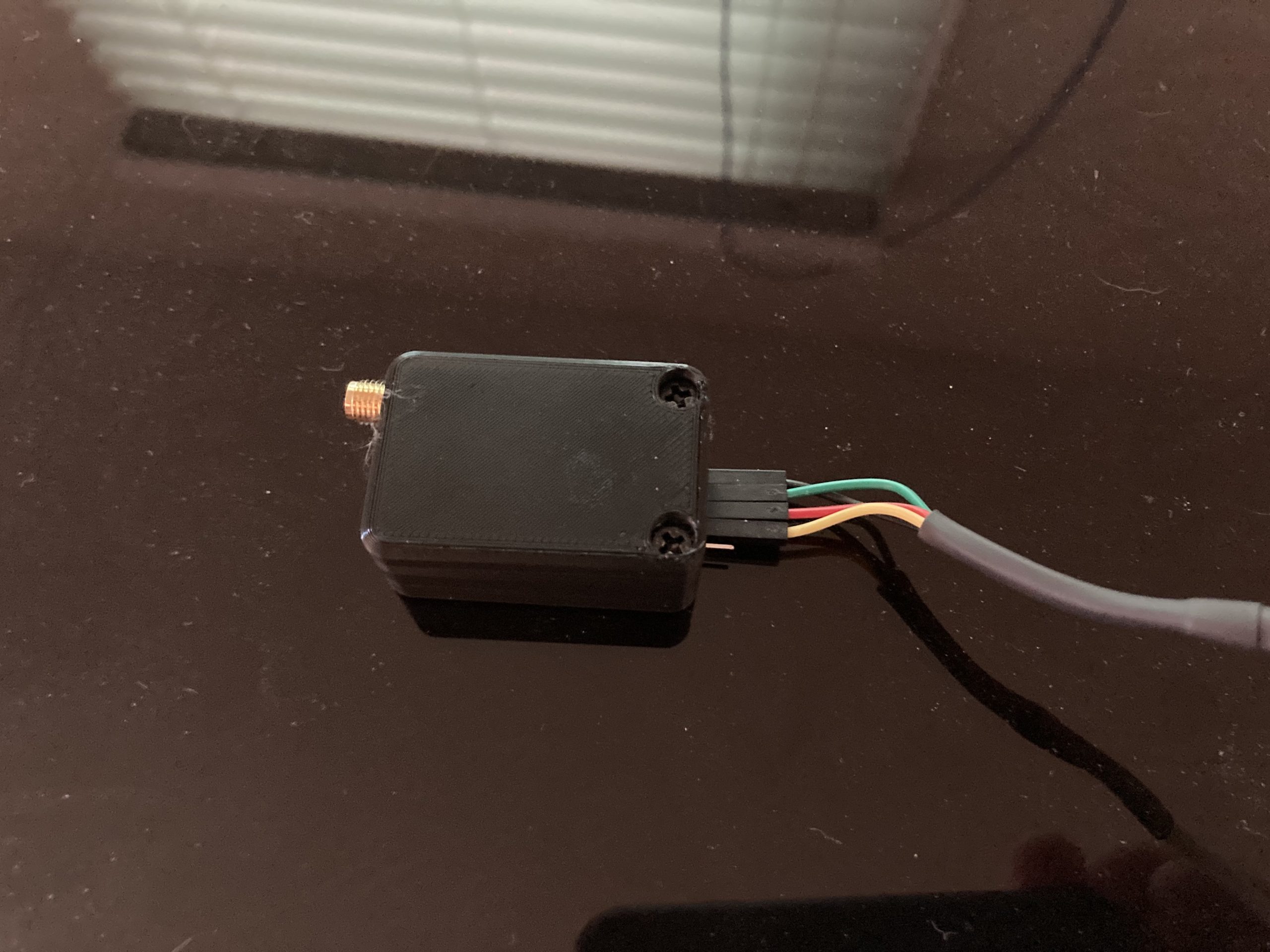
What a super easy project and I confirmed it is working by setting my zip code to 47715 in Indiana (I am in North Carolina) and then plugging in the GPS. Within seconds it began to load the full database for North Carolina. So I can state that it works, and it works really well, even with no external antenna.
Confirmed! This worked perfectly, and spending $11 for the module and putting in a bit of wiring effort beats the crap out of $90 for Uniden’s kit!
Thanks for a very helpful guide.
73 de KC7GR
Thank You! Very helpful. Solid and inexpensive solution.
Pingback: USB GPS Uses - John's Tech Blog
Just an FYI on the new module that you linked to it requires an external antenna. The built-in antenna barely works at all even when outdoors.
Yep. Mine actually works indoors but I have a half a dozen other similar modules that don’t. Probably depends on a lot of factors. Mine is on an outside wall by a window.
Hi John
I was wondering if you knew how I could wire an internal GPS Unit into a SDS 100. There was a gentle man who did it and said he would share the info on wiring in the GPS unit. However he never came thru. So, I thought I’d ask you.
Thanks for any help you may be able to privide