I am neither prepper nor survivalist but I do get a kick out of being somewhat self sustainable. At the end of this I hope to achieve a working knowledge of solar systems and to possibly apply that knowledge to a larger scale application of a solar installation.
Make your own free electricity. No taxes, no smart meter checking your consumption. Yeah, well, we’re not making that much electricity here.😃
My intent here is to make a 12vdc system with a Lithium Iron Phosphate (LiFePO4) battery and create 1000 watts of AC power via a pure sine wave inverter. 1000 watts won’t carry you too far or too long but with the right component mix you could do some large essential tasks like maybe run the washing machine or watching TV for several hours. Small current drawing appliances like LED lights and items like that will run for ages.
Believe you me even though I know a thing or three about electricity, solar is a slightly different animal. Maybe the best resource to learn about Solar is through this YouTube Channel and in fact my build below is mostly his simple DIY design and choice of components with a tiny tweak or two.
The system I want to build will be comprised of the following components:
- Two 100 watt Renogy 12 volt Solar Panels (and associated cables and branch connectors)
- 20 Amp MPPT Solar Charge Controller As an almost immediate regret I should have bought a 30 amp controller. My system is maxed with 200 watts of panels almost with a 20 amp controller.
- Remote LCD display for Charge Controller
- 12 vdc fuse block (comes with only 1 15 amp fuse)
- GoWISE Pure Sine Wave Inverter
- Battleborn Lithium Iron Phosphate Battery (or Batteries). Right up to this point this is fairly affordable. These batteries are about $1000 each. SAY WHAT? Yes, it’s true. Can I use cheaper Lead Acid Batteries………sure. But lead acid batteries are not usable when depleted below 50%. Also if you let them drop below 50% repeatedly, you’ll kill them. I know. I just killed one that was only a couple years old. Also Lithium Iron Phosphate batteries last a decade or more and even then they are usually still working at 80% or more of capacity.
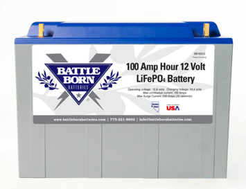
Battle Born Battery LiFePO4
You can also use a Lithium Iron Phosphate battery down to about 15% or so of capacity so it will take you a lot further than Lead Acid or AGM batteries will.
In fact if you look on eBay people pay BIG BUCKS for Lithium Iron Phosphate batteries that are used and that come out of critical medical equipment. The batteries are still good but just have lost some efficiency. So buying used batteries is a viable option.
Also there are all manner of Chinese cells on the market which are good however they need to be operated with Balance Controllers which complicates things somewhat. The batteries I listed about do all the heavy lifting already. You don’t need any other components to maintain the system.
So I will initially buy one and maybe add a second one later. Anyway if I’ve come out the backside of a storm I want as much useable power available to me between periods of sunshine as humanly possible. No fun losing the fan at 3 AM or the refrigerator for that matter.
Time to Build! First we’ll start with 2 – 100 watt panels wired in parallel. When tested with no load it should read 22.5 volts (open circuit voltage). When wiring in parallel the voltage stay the same but the amperage doubles. If a panel puts out 5.5 amps as advertised then I should be getting approximately 11 amps. My pic shows 21.9 volts but a split second before it said 22.5. Clouds and stuff.
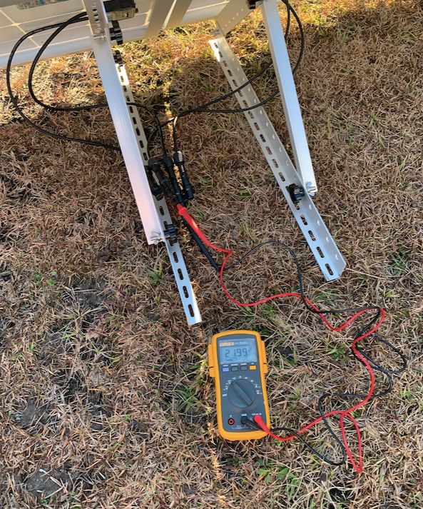
2 – 100 watt Renogy Solar Panels wired in parallel testing open circuit voltage
And finally the 2 panels mounted on cheap tilt mounts.
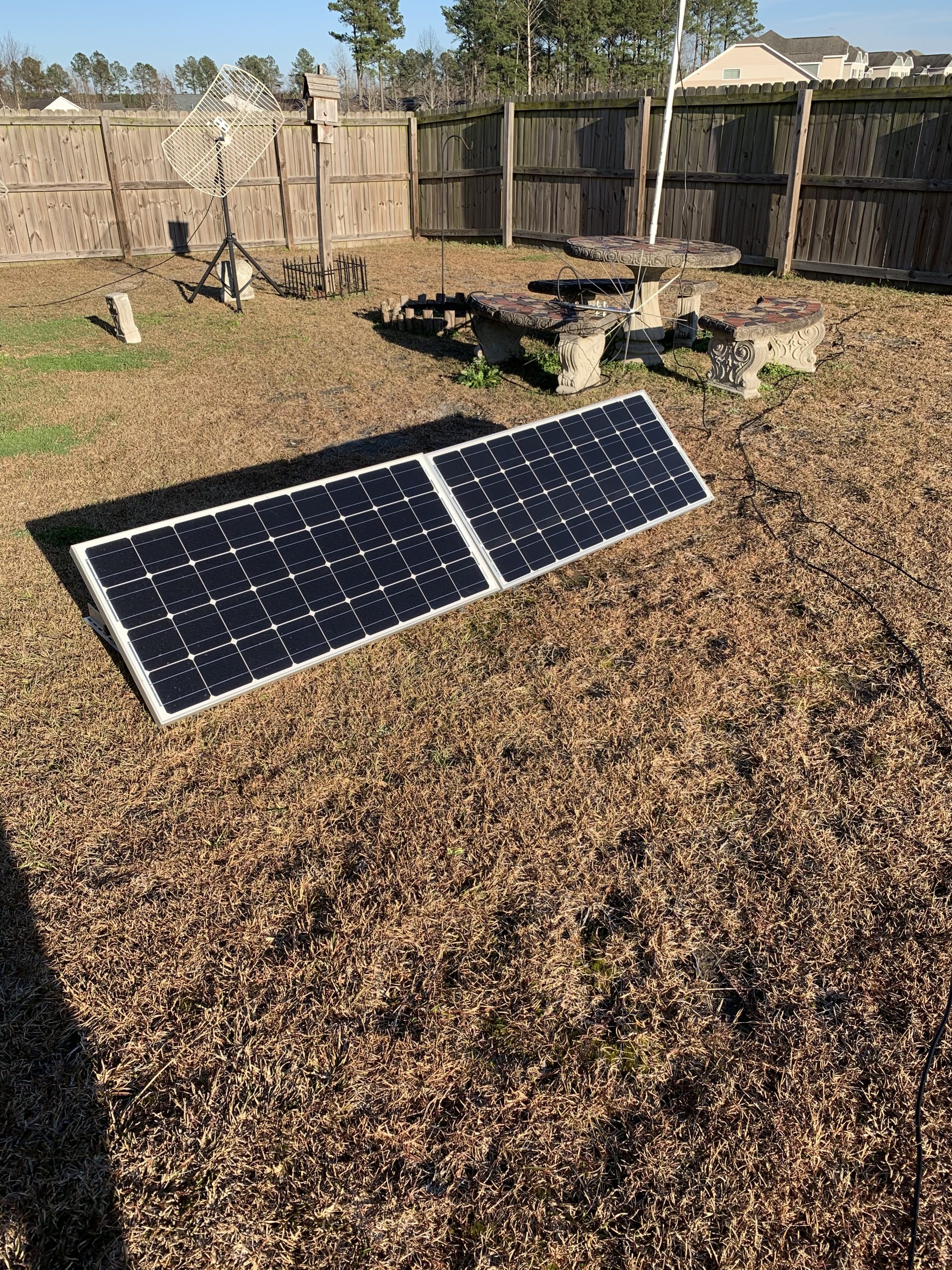
Two Renogy 100 watt solar panels
Ok, that’s the outside stuff. Now for the great indoors. I’m mounting the project components on a 2’x4′ piece of plywood. Ultimately there will be an inverter to power up to 1000 watts of AC appliances (not a lot of power, but it is enough for emergency power supply for sure). Also I’m going to add some 12 vdc plugs so I can power 12 volt appliances. In a power out scenario I can light some LED lights, keep a small fridge going, power a radio and TV, and maybe run a 12 volt fan or something. Provided I get good sun I could hopefully have enough battery storage to keep things going good at night. This isn’t primary survival, although it could be in a horrible situation but I view this system as helping me conserve on gasoline for generators or living off grid in the camper for a few days or a week. Lifeboat situation.
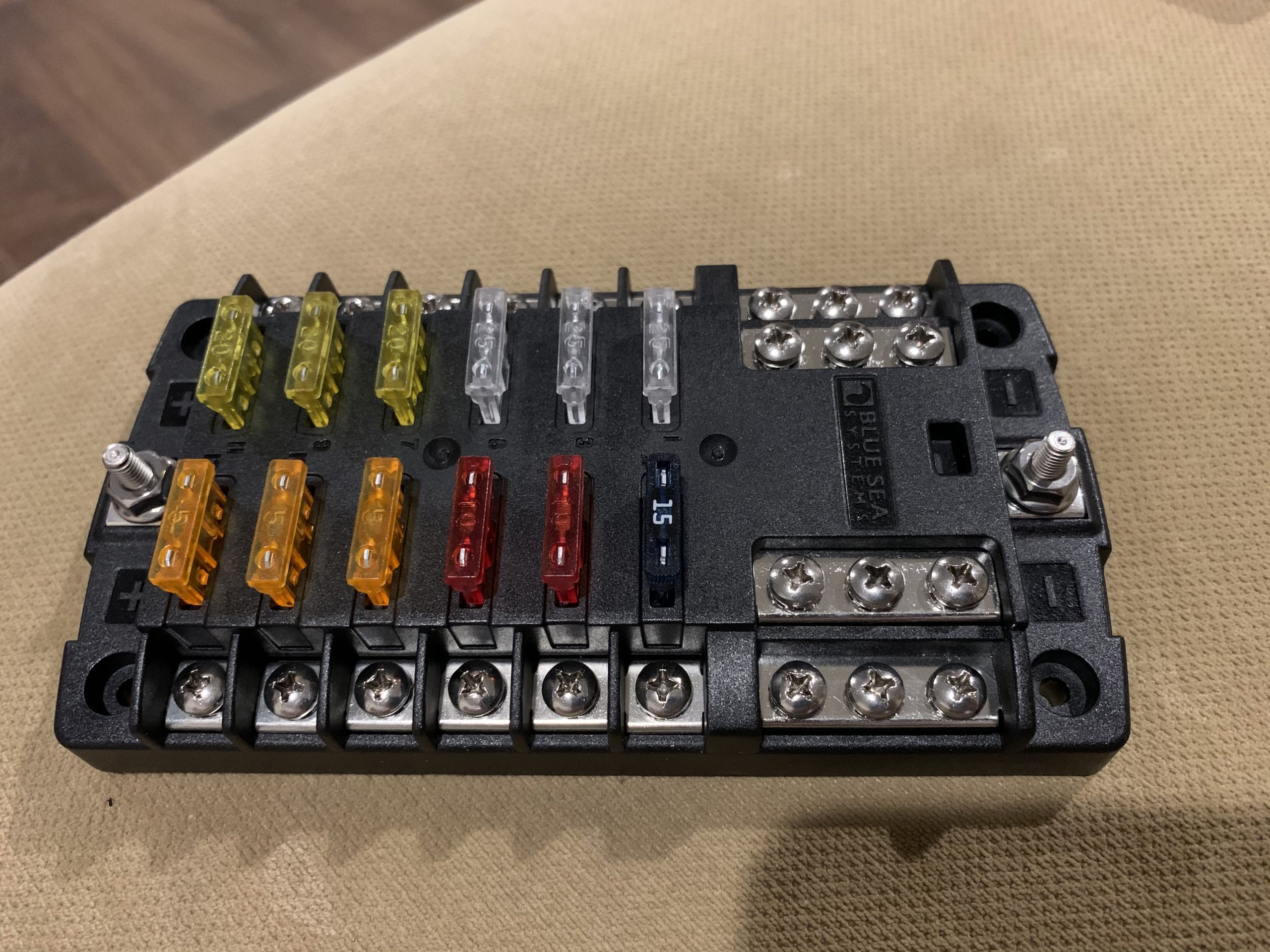 To run all those 12 volt appliances a fuse block is added in the build.
It has 12 positions however you probably shouldn’t load it up too much. I’ll add a couple of 12 volt, cigarette lighter style charging ports with a USB charger.
I have a few 12 volt appliances such as an Alpicool 12 volt portable refrigerator, and a Black and Decker Inflator.
Right after that I think the only other practical thing hanging off this very small system could be a string of LED lights.
Also be advised of the fuse size you use. I’ll use a 25 amp fuse (clear to gray color) after the charge controller and those cigarette lighter ports are typically rated for 10 amps (red fuse). Depending on your LED lights they could probably hang off the 5 amp (orange fuse).
Again, just because there are 12 hookup points doesn’t mean I should be using 12 hookup points in such a small system.
Here’s the plan:
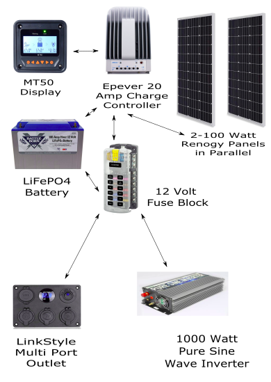
Block Drawing Of Minimalist Solar System
Now let’s mount the components on a board.
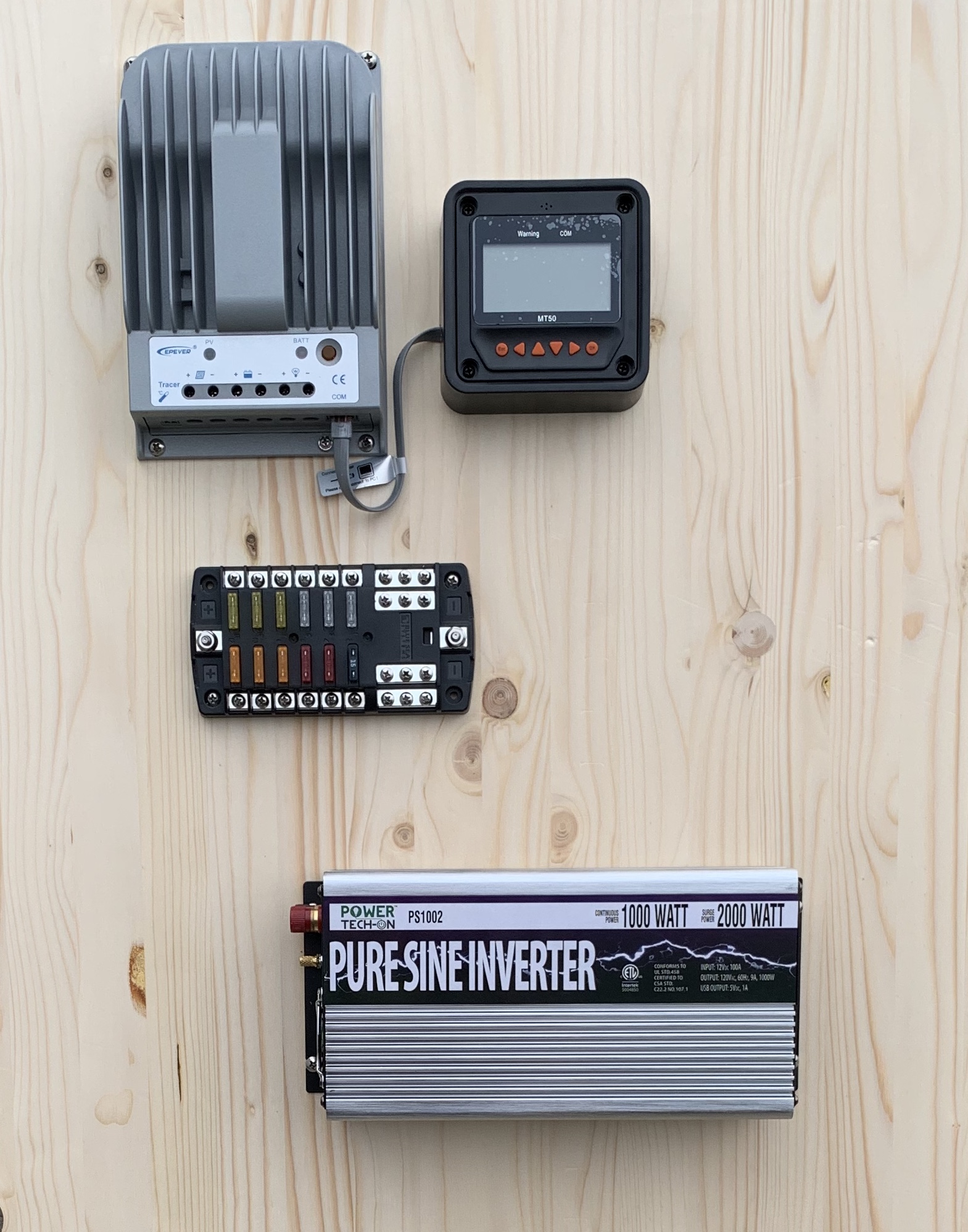
Board mounted components
Mounting the 4 components was pretty easy but the MT-50 display screen was a little weird. If you plug in the RJ45 connector it hits the board so I took a 13/16″ wood bit and bored into the wood a bit without drilling through (in case I ever want to use the back side of the board for something). The RJ45 connector is now not smashed into the mounting board.
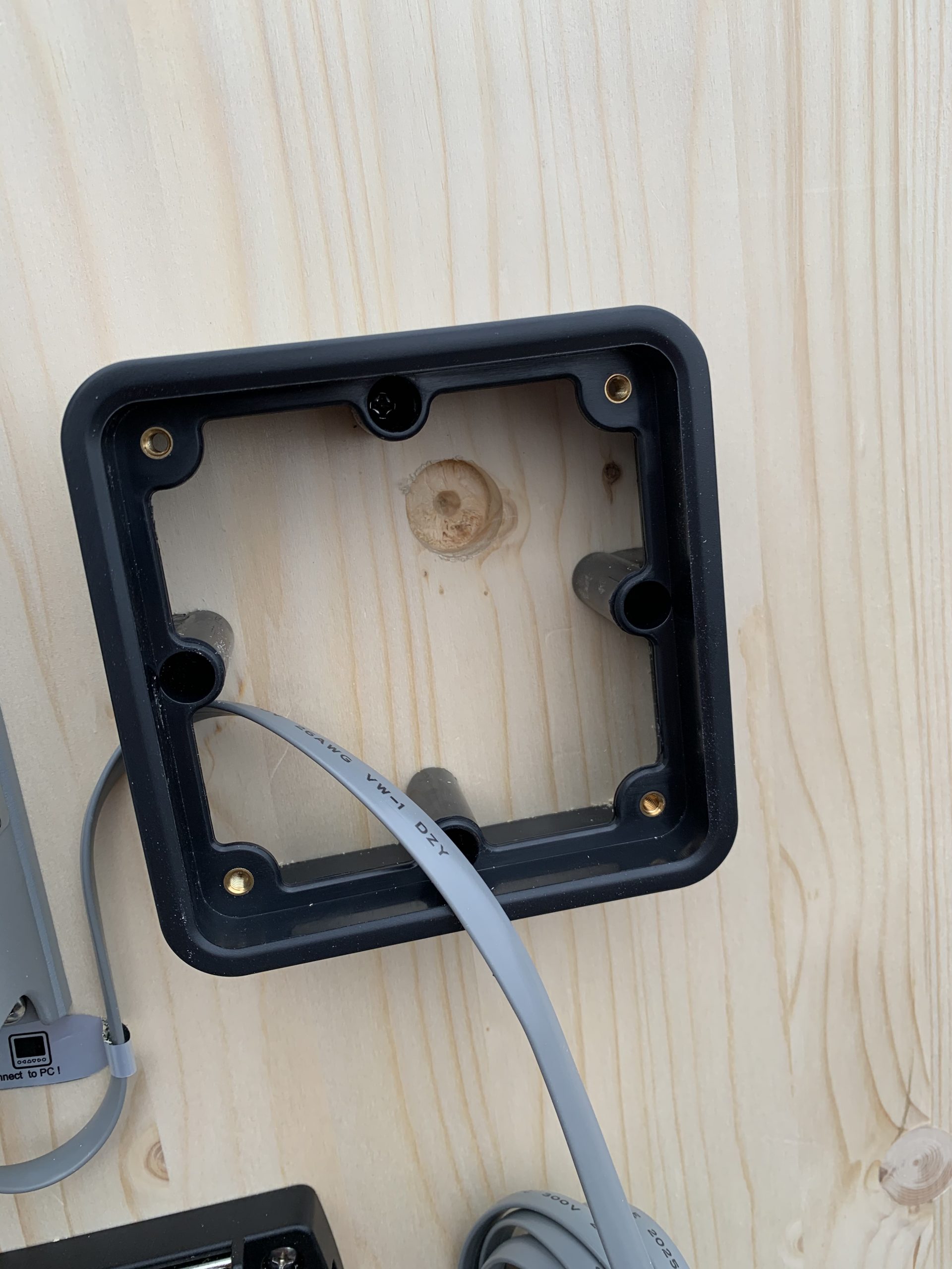
Hole to allow RJ45 connector to not get crushed on the panel
Even the excess cable if rolled up neatly fits inside and under the screen making for a much cleaner installation. Now, on to wiring this thing up.
First and foremost we need to be SAFE. This is electricity we are dealing with. Wiring this up with whatever hunks of wire you have laying around can cause overheating and possibly a fire. You have got to be sure to use the appropriate gauge wiring in the appropriate locations. Be sure to read the manual for the solar panels, the charge controller, the battery, and the inverter to ensure wiring specifications are met.
Now here’s a picture of it all wired up:
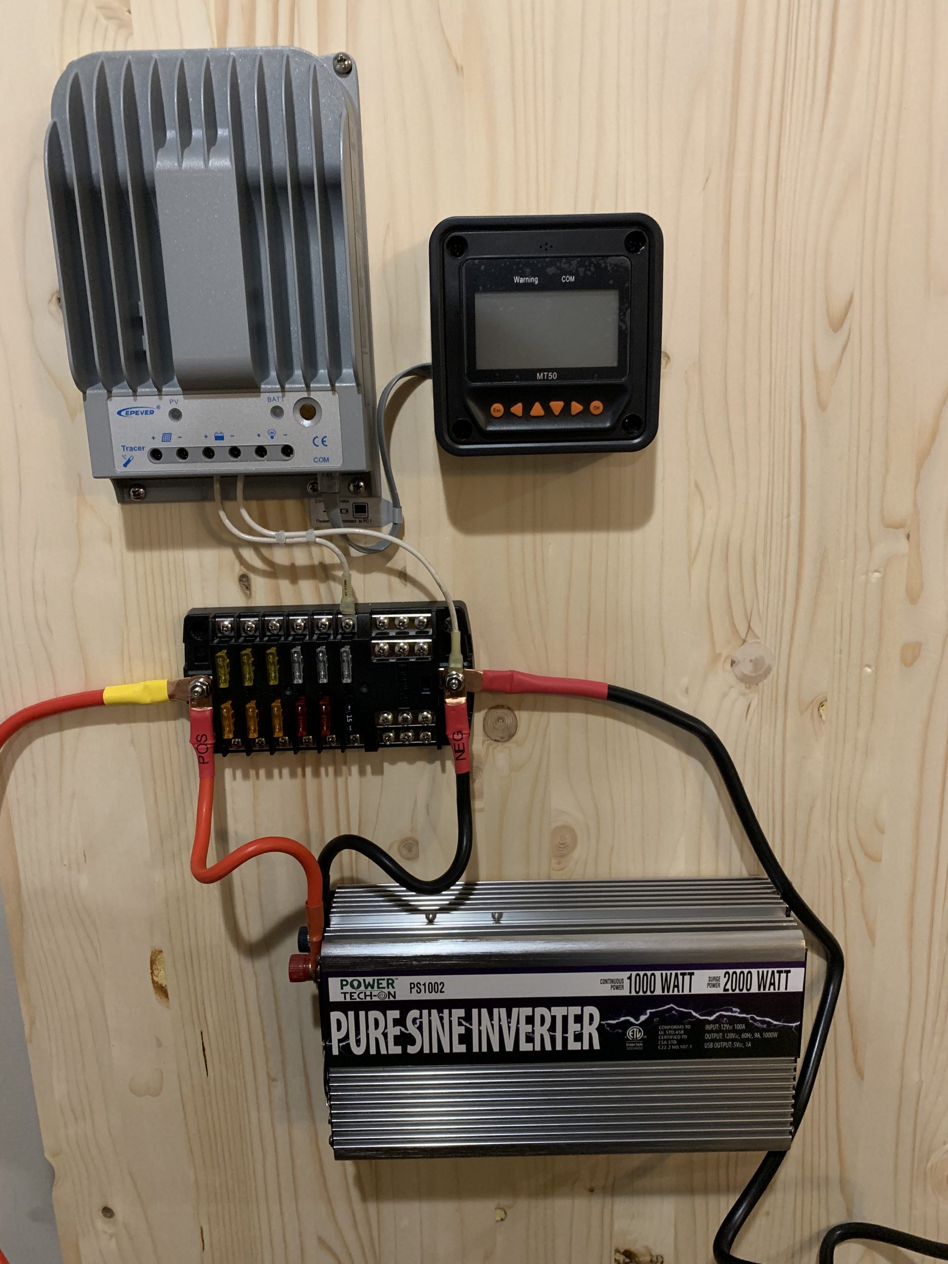
Wiring configuration
It is just six wires (for now). Super easy.
- Battery connection + (10AWG) to 25 amp fuse on fuse block
- Battery connection – (10AWG) to negative post on fuse block
- Positive (red) inverter wire (supplied with inverter) to positive post on fuse block
- Negative (black) inverter wire (supplied with inverter) to negative post on fuse block
- Positive (red) wire (4AWG) from positive post on fuse block to battery
- Negative (black) wire (4AWG) from negative post on fuse block to battery
To make things neat I 3D printed some clamps I got from here. I used the 5mm radius clip (10mm) and upsized it to 110% since #4 AWG is typically 11 mm diameter.
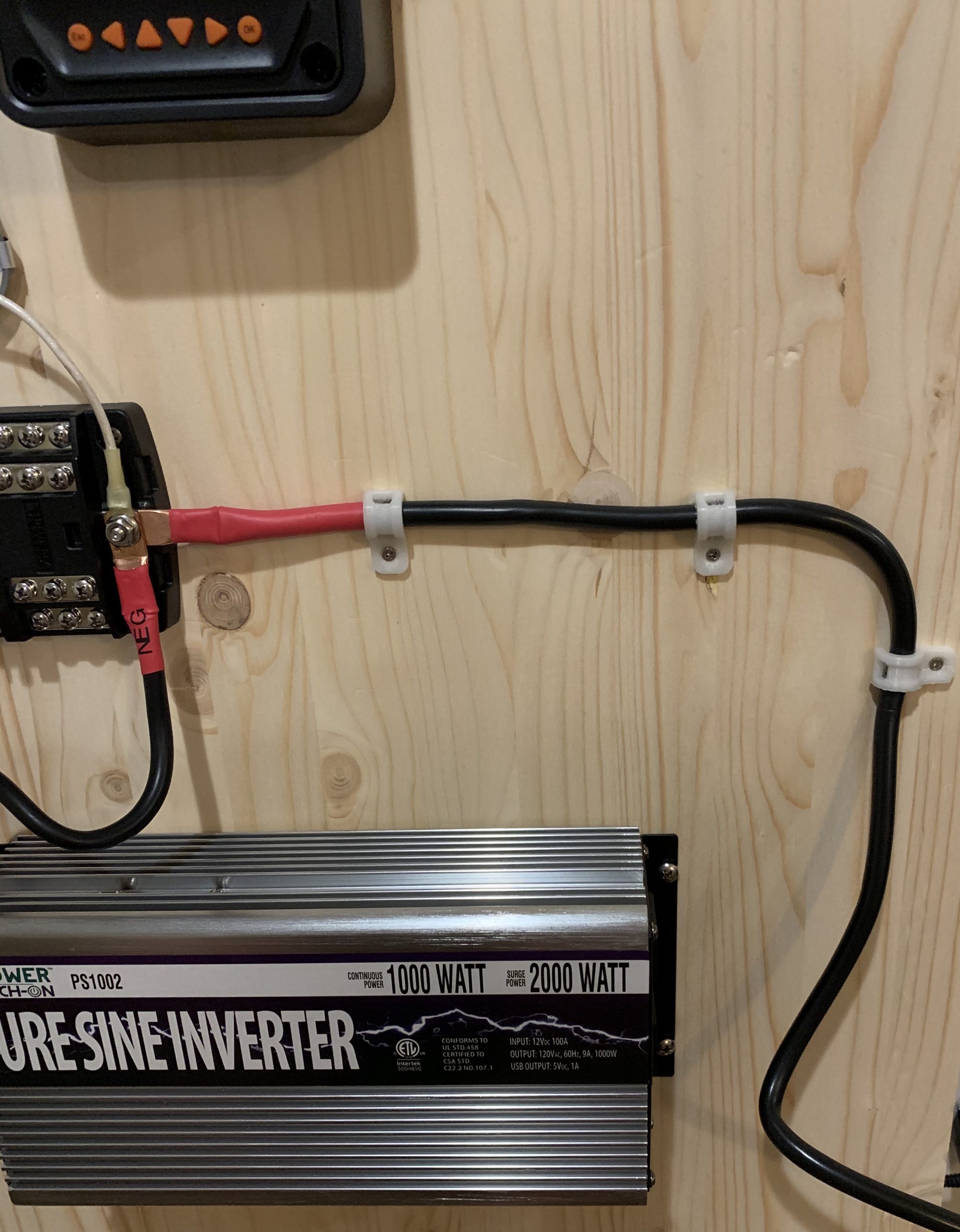
Wire Management with 3D printed clips
We can now connect the system to the battery and test the MT-50 display and charge controller.
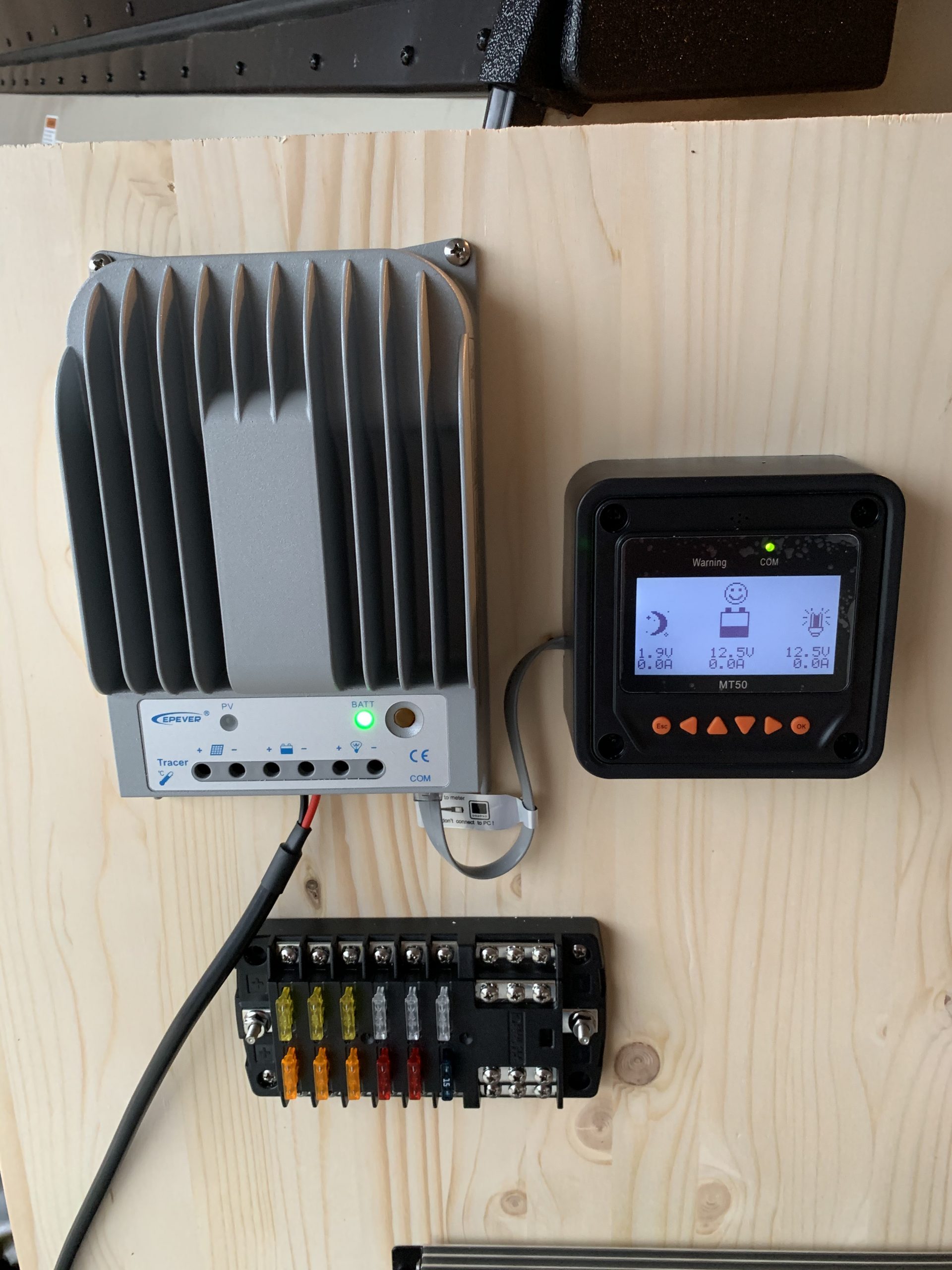
Operation of MT-50 Display
Perfect! Now we need to ensure the charge controller is set with the proper charge parameters depending on what type of battery we have.
The controller will charge Sealed, Gel, and Flooded batteries but it has a custom USER profile that can be modified to allow for charging of lithium batteries. Since I have the BattleBorn LiFePO4 battery then I’ll have to change the following parameters from the MT-50 controller:
NOTE: I kept getting para.errors and then I found out if you work from the bottom of the list to the top it works for some reason. Not very intuitive but it’s what you have to do. These settings were provided by BattleBorn Batteries specific to the Epever Tracer MPPT controllers.
- Under “User” Settings
- Over voltage disconnect voltage
14.7V - Charging limit voltage
14.6V - Over voltage reconnect voltage
14.6V - Equalize charging voltage
Off or 14.4V - Boost charging voltage
14.6V - Float charging voltage
13.6V - Boost reconnect charging voltage
13.2V - Low voltage reconnect voltage
12.0V - Under volt. warning volt
11.5v or Off
Since this is first and foremost a 12 volt system I decided to add two USB ports and a 12 volt cigarette lighter style power port. The USB’s are wired to a 5 amp fuse and the power port is wired to a 10 amp fuse. Pushed the wires through the back of the board to keep it neat.
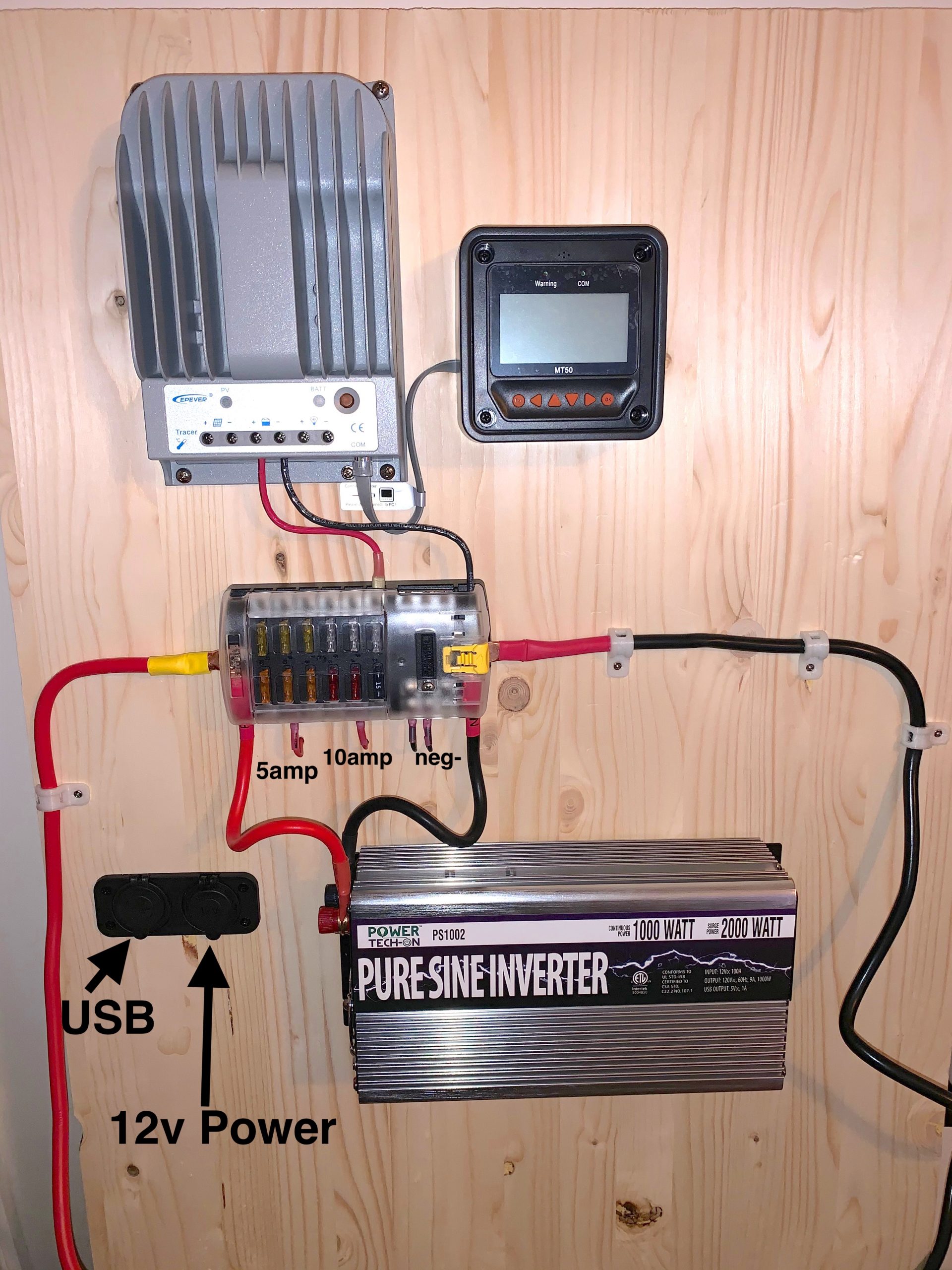
USB and 12 volt power ports added
The 2 port USB/12v outlet didn’t last long. I decided I needed a switch on it to kill the blue LED light that stayed on 24/7. So I added a Linkstyle multi-port panel with USB and 3 12 volt ports. It is switched and also has a voltage display on it. Nice touch.
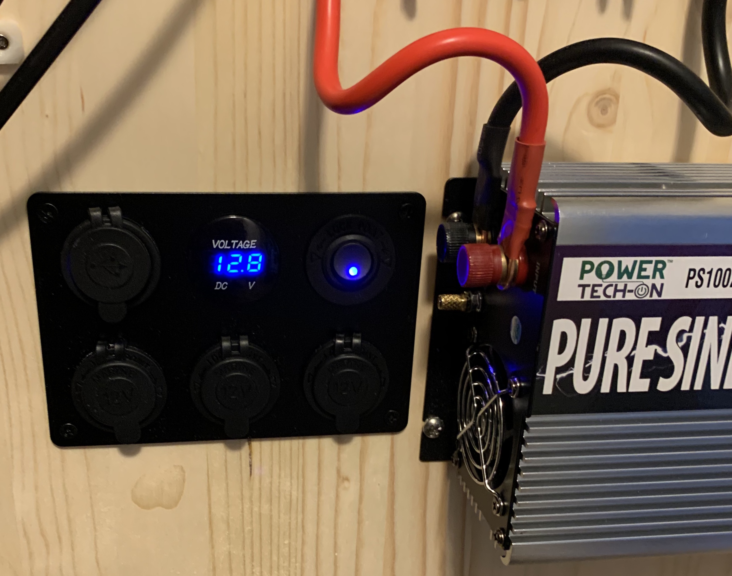
Linkstyle Power Panel
Couldn’t wait for the Lithium Iron Phosphate battery so I decided to hook this to my parallel camper batteries which are flooded. I set the charge controller to “flooded”, hooked the battery leads up and then connected the solar panel. Everything worked exactly as it should. I’ll have to do a little endurance testing however since this is my camper which I actively use and which I just bought two new batteries for I’m not going to do anything weird to kill my batteries such as deplete them.
[kad_youtube url=”https://www.youtube.com/watch?v=HEhpB8dBrCY” ]
And………..This is the system installed and operating!
[kad_youtube url=”https://www.youtube.com/watch?v=5yQPm7Ep7gI” ]
