My OpenVPN Connect app on my iPhone just quit working. This is how I kicked its ass.
I have been a big fan of Virtual Private Networks for YEARS. If you are on an untrusted connection such as Airport or Hotel or Coffee Shop the safe play is to connect to a VPN which encrypts your communications in a tunnel between your computer and your VPN server. It wildly increases security.
So for years I have run an OpenVPN server on my hardwire firewall which runs an OS called pfSense. If you have any inkling of security at all you should run a hardware firewall. But that is a discussion for another day. Anyway pfSense has an easy configuration for OpenVPN with a client export feature that is second to none.
However, the IOS OpenVPN app JUST QUIT WORKING. I can connect to my VPN but traffic doesn’t seem to move. I can’t do anything with it at all. So I hit the OpenVPN IOS forum and sure enough……..this is a thing. Since October 2018 as well! To confirm this is the problem I can connect to my OpenVPN server JUST FINE with my iPads which have the older app.
You see all these Home Security systems being advertised all the time and they all have one gotcha. Some kind of charge every month. Why not just make your own? Also it costs PENNIES on the dollar compared to some of those others.
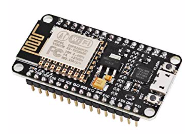
One of the biggest components of home security is knowing the state of windows and doors. And that is very simple to obtain and with INEXPENSIVE hardware. This guy is the backbone to this project:
This is a NodeMCU ESP8266 Internet of Things (IoT) chip. Translation: It’s a little teeny tiny small board computer with a wifi antenna on it.
You can get ESP8266 devices WAY cheaper than this even though this guy only costs $9 or so. A couple of things I like about it are that it has a Micro USB input connector on it and the legs are already soldered on.
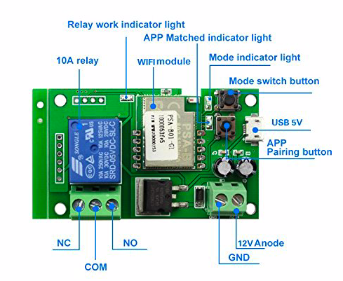
If you have dabbled in Home Automation you’ve probably heard of Sonoff. They make all manner of home automation devices. I’ve been largely ambivalent towards them as I prefer Z-Wave devices and hackable outlets to power most of my home automation needs. But I kept READING ABOUT THEM. Everywhere you turn on the Home Automation sites people are talking about Sonoff and something called “Tasmota Firmware”.
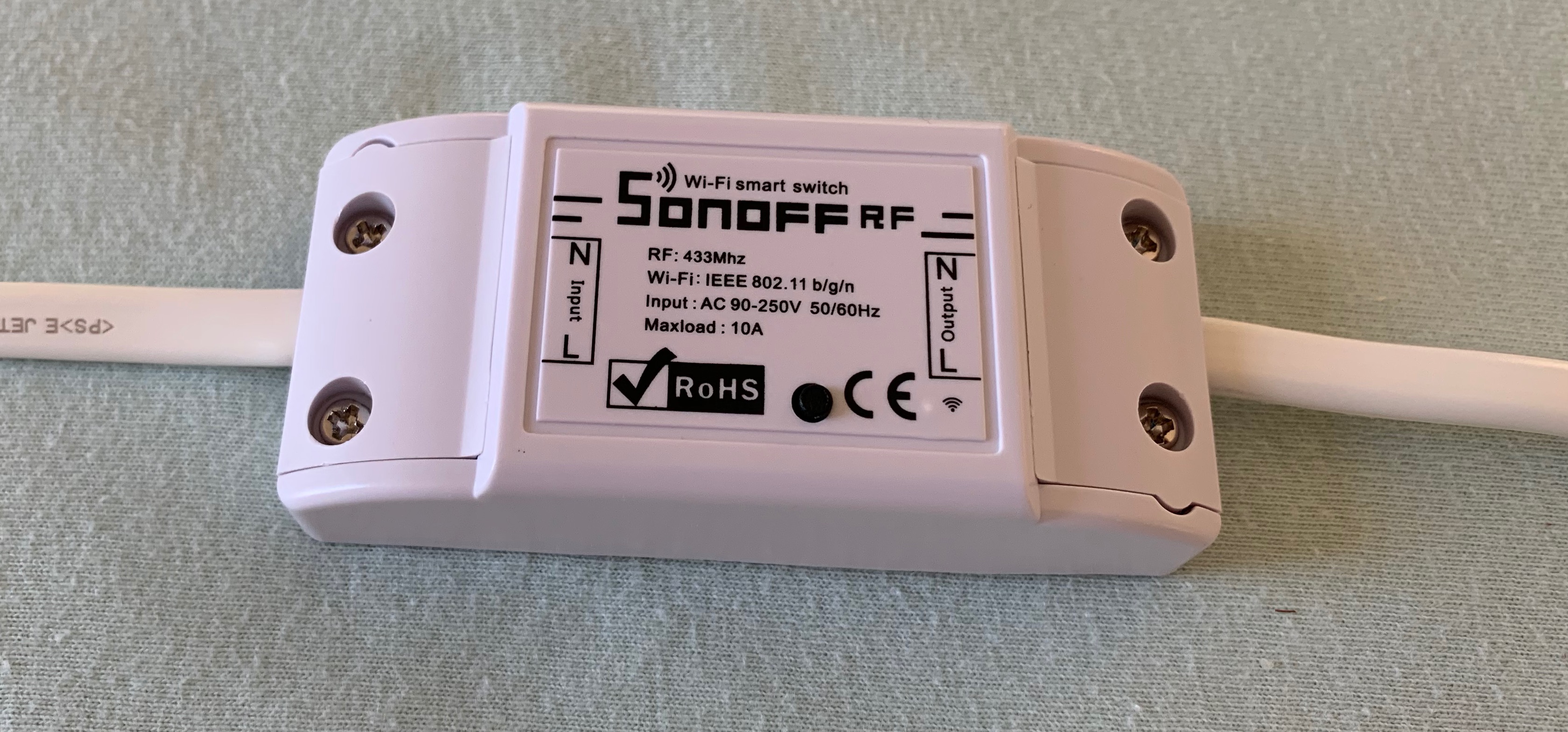
I decided to see what all the fuss was about and ponied up the requisite $11 for a Sonoff RF from Amazon. I’ve been on a 433 MHz device kick lately and I like the fact that radio controlled devices can work even when the network goes down. As long as a Raspberry Pi is on that delivers that radio burst…….BOOM……the lights go on and off.
So I got one just to play with. The interesting thing to me is that not only is it 433 MHz radio controlled it also works with WiFI and if you flash it with Tasmota Firmware it will do MQTT as well. Okay, I’m getting slightly impressed here.
Last week I showed you how you can capture the remote codes for cheap radio controlled electrical outlets and this week the theme is 433 MHz MOTION SENSORS. With a properly configured motion detector you can then trigger that outlet. For example……..when you open the pantry door the light comes on………when you walk in the laundry room, the light comes on……..when someone presses the smart doorbell, the lights come on. Pretty handy stuff.
Most home automation motion sensors send TWO signals. One when they are tripped and one when they reset. Most of them will stay tripped for a predetermined amount of time. Usually for 2-4 minutes or so. Good idea to know the state of the motion detector BEFORE you buy it.
For example I have a motion detector with a 4 minute reset on it in my garage and laundry closet. That means that both of those lights that get triggered are staying on for 4 minutes whether I like it or not (unless I write some crazy code).
But some of these cheap sensors send ONE signal. “I’m ON” and that’s it. They don’t reset. That provides a challenge. This is one such sensor I bought (and DEFEATED).
It costs about $12 now and you can get them even cheaper. I got this for an outside sensor.
Anyway it does have some user control as inside there are two DIP switches. One sets the sensor state for 5 seconds or 5 minutes and the other one turns the LED indication it has been tripped on or off.
If you want to be stealthy, turn off the LED. I personally like the bad guys to know they got got.
Anyway before you can do this you must capture the code with a program called RTL_433. I discussed this in another blog.
RTL_433 And Home Assistant Set Up
MQTT 433 MHz Motion Sensor
Once your hardware is set up (an RTL-SDR device) you run this command on that pi to send THIS code below. The last part would only be necessary if your mosquitto MQTT server is on another device. Mine is.
Now that will take all the messages it receives from the SDR device (on 433.920 MHz) then it publishes a message on your MQTT server that looks like this:
Now we have to extract that data to make sure we hone in on this device (because I have multiple devices on this same MQTT Topic). In your HomeAssistant configuration.yaml file you add the following to create a binary sensor.
binary_sensor:
  - state_topic: home/rtl_433
    name: Garage Motion
    value_template: >
    {% if value_json is defined and value_json.id == 924442 %}
       {{ value_json.state }}
    {% endif %}
    payload_on: 'motion'
    off_delay: 5
    qos: 1
Whew! You can see I have it so it only takes information from sensor id #924442 and when the “state” = “motion” then it triggers the binary sensor. Then the line with:
off_delay: 10
Sets the sensor back to the OFF position after 10 seconds. So with a ONE signal sensor I can turn the state to OFF after how ever many seconds I want. That garage light will now go out after 1 minute or 2 minutes or 2 seconds……..whatever I want.
Well……It works PERFECTLY. Here’s what the tripped state looks like:
Now I can start making some automations to use with my $10 motion sensor. Open the pantry door……..the light comes on……….hence the name “Pantry Motion”.
Automations For 433 MHz Motion Sensor
So what I did here was to make an automation to turn on one of my inexpensive outlets. Eventually this will be tied to a smart light or smart switch. Right at this moment I have no smart light nor have installed a smart switch in the pantry. Changing the line of the entity_id in the action part of the code can turn basically any device on or off. Because the code above leaves the sensor state on for 10 seconds, running the automation means the “light” (in this case outlet) will be on for 1 minute. Pretty cool, huh?
automation 21:
  alias: Den Outlet Motion Sensor
  trigger:
    platform: state
    entity_id: binary_sensor.pantry_motion
    to: 'on'
#  condition:
#      condition: state
#      entity_id: sun.sun
#      state: below_horizon
  action:
    service: switch.turn_on
    entity_id: switch.den_outlet
automation 22:
- alias: Den Outlet Motion Sensor Off
  trigger:
    platform: state
    entity_id: binary_sensor.pantry_motion
    to: 'off'
    for: '00:00:50'
  action:
    service: switch.turn_off
    entity_id: switch.den_outlet
Notice that I have # marks in front of the condition statements. In many cases you wouldn’t want a light to come on until after dark. I left that in there to easily change it back if I find I don’t need the light on in the daytime, but hey, it is essentially a windowless closet.
Here’s a video of how it all works. I shortened the sensor time for the purpose of the video.
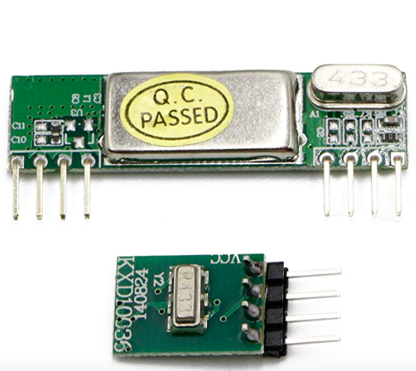
I’ve been dabbling with 433 MHz devices over the past few days and tying those devices in with my home automation software named HomeAssistant. A decent transmitter receiver kit will set you back a whopping $10 or so. I opted for this one.
It performs extremely well in a home environment and has great specs.
One of the gotchas of this device though is it comes with ABSOLUTELY NO DOCUMENTATION WHATSOEVER. You’d be hard pressed to find much useful on line as well. So that’s where I come in.
Fortunately the wiring is pretty basic and the pins are clearly marked on the back side of the circuit boards.
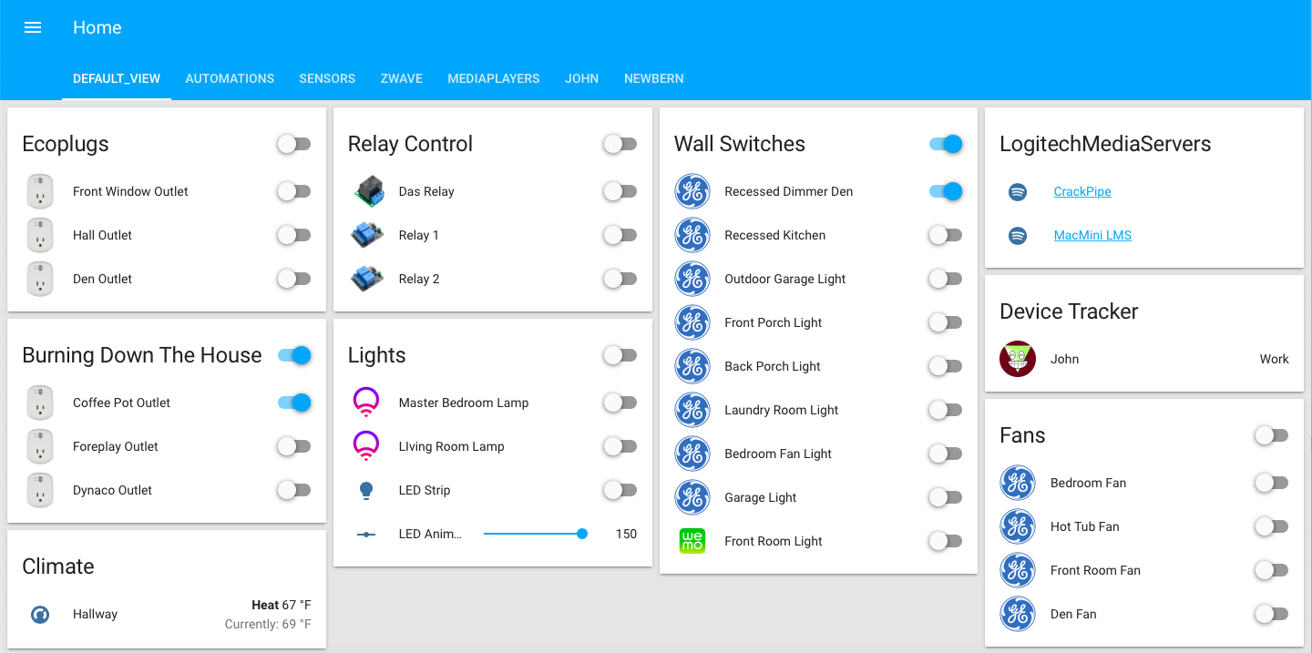
I have what I consider to be a pretty extensive Home Automation setup.
I use the program HomeAssistant on a Raspberry Pi3 with an Aeotech ZWave controller . Also I have some wifi devices such as a Nest Thermostat, Ring Doorbell, Ethernet Security Cameras, a WiFi Light Switch, and some smart light bulbs.
Hobbies are fun. Hobbies are hard. If you have a hobby you somehow or another want to document it for posterity. If you own widgets such as Swiss Army Knives, Coins, trinkets, whatever then still photography is probably your medium of choice to preserve and document your collection.
But, let’s face it. Most of us suck at photography. If only there were a way to use a computer to improve your photography skills…….oh wait, there is. It is called “Tethering” and tethering is nothing new. I can’t provide a history lesson but I know I’ve been doing it since the late 90’s or so and it probably came along right with the advent of digital cameras, whenever that was.
What’s a Spyserver? And why would you want one? Spyserver is a program for a Software Defined Radio (SDR) that allows you to access that radio from anywhere. It also allows you to share your radio from anywhere and you can likewise share other people’s SDR radios. Why would you want to do that?
First when the word “radio” comes to mind we tend to think of AM or FM radio only. An SDR device is so much more than that. It can literally listen to things from 0 kHz to 2 GHz or so. That’s EVERYTHING that you can think of that uses a radio signal. Short Wave, CB, Ham, pagers (yep they still use pagers), Police, Fire, EMS, the Space Shuttle flying overhead (not kidding), the tire pressure monitor sensors on your car, tracking aircraft, tracking ships, tracking weather balloons…………the list is almost endless.